Rockwell Automation 1403-DM_LM_MM Powermonitor II Instruction Sheet User Manual
Page 66
4-30
General Operation
1403-IN001A-US-P
Real Time Clock Status
Battery Usage Timer Value
This value indicates the number of days that the
Powermonitor II Master Module has been in Battery
Backup mode. The timer only increments when the
Master Module is without control power. The timer is
not automatically cleared and must be manually
cleared when the battery is changed.
Note:
Typical battery replacement is ten calendar
years or 2,000 accumulated days, whichever
comes first.
Smart Communication Card Status
Smart Communication Card Type
Smart Communication Card Firmware Revision
Number
This parameter returns the firmware revision number
of the Smart Communication Card. This value is
returned through the Smart Communication Card as
an integer such that 1.00 is represented as 100.
Number of Display Modules
This parameter indicates the total number of Display
Modules currently connected within the fiber optic
loop.
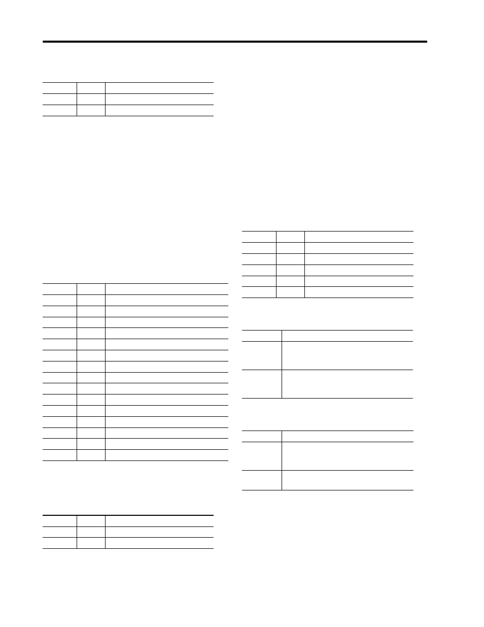
Display Module Status
Display Module Self-test Results Word 1
Display Module Self-test Results Word 2
Bits
Hex
Description
bit 0
0001h
Summary status
bits 1-15
Reserved for factory use
Bits
Hex
Description
bit 0
0001h
Summary status
bit 1
0002h
16-bit walking ones status
bit 2
0004h
16-bit walking zeros status
bit 3
0008h
16-bit data bus status
bit 4
0010h
8-bit walking ones status
bit 5
0020h
8-bit walking zeros status
bit 6
0040h
8-bit data bus status
bit 7
0080h
16-bit device write status
bit 8
0100h
8-bit device write status
bit 9
0200h
NSC EPROM CRC status
bit 10
0400h
NSC dual read/write status
bit 11
0800h
NSC no read/write status
bit 12
1000h
NSC serial communications status
bit 13
2000h
NSC serial communications RAM status
bits 14-15
Reserved for factory use
Bits
Hex
Description
bit 0
0001h
R I/O, RS-232/RS-485
bit 1-15
Reserved for future use
Bits
Hex
Description
bit 0
0001h
Summary status
bit 1
0002h
Display Module 1 status
bit 2
0004h
Display Module 2 status
bit 3
0008h
Display Module 3 status
bits 4-15
Reserved for factory use
Bits
Description
bit 0-7
(Byte 1)
Display Module 1 self-test results
0001h = Unsuccessful ROM self-test
0011h = Unsuccessful RAM self-test
bit 8-15
(Byte 2)
Display Module 2 self-test results
0001h = Unsuccessful ROM self-test
0011h = Unsuccessful RAM self-test
Bits
Description
bit 0-7
(Byte 1)
Display Module 3 self-test results
0001h = Unsuccessful ROM self-test
0011h = Unsuccessful RAM self-test
bit 8-15
(Byte 2)
Reserved for factory use