Status inputs – Rockwell Automation 1403-DM_LM_MM Powermonitor II Instruction Sheet User Manual
Page 28
2-16
Installation
1403-IN001A-US-P
Analog Input
This input is intended to accept input signals of zero
to one volt AC, 50/60 Hz, rms or plus/minus (±) 1.4
VDC.
Use twisted pair or shielded pair cable to reduce the
level of noise that may be induced on this low level
signal.
Do not use ground as a return path. A Ground
Potential Rise will add to or subtract from the input
signal level and affect the reading.
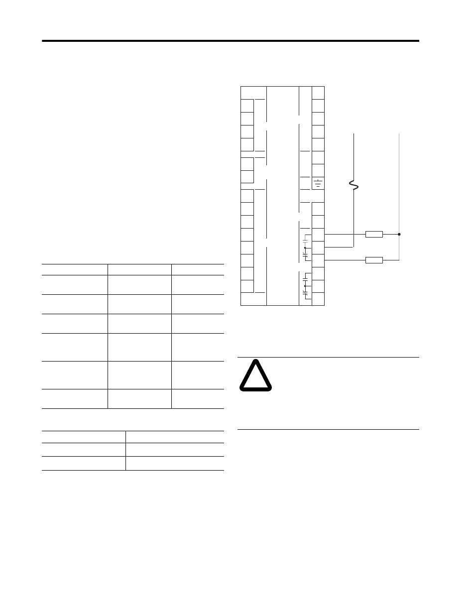
Relay Outputs
(Isolation Ratings = 2500V)
Figure 2.14 shows one of the internal Form C Relay
contacts along with an example of customer wiring to
a supply voltage and two loads.
Figure 2.14 Control Relay Connections
Status Inputs
All Status Inputs are common to an internal 24VDC
source on the SCOM terminal. Status input terminals
1-4 are positive polarity and SCOM is negative
polarity.
To prevent ground loops, each wire run to a Status
Input should have an accompanying return wire
connected to the SCOM (the common point for all
Status Inputs). (If more than two Status Inputs are
used, an external terminal block is recommended.)
Table 2.1 Contact Ratings
Rating
50/60 Hz AC rms
DC
Maximum Resistive
Load Switching
10A at 250V
(2500VA)
10A at 30V and
0.25A at 250V
Minimum Load
Switching
10mA at 24V
10mA at 24V
UL 508, CSA 22.2,
IEC Rating Class
B300
Q300
Maximum Make
Values Inductive Load
30A at 120V
15A at 240V
(3600VA)
0.55A at 125V
0.27A at 250V
(69VA)
Maximum Break
Values Inductive Load
3A at 120V
1.5A at 240V
(360VA)
0.55A at 125V
0.27A at 250V
(69VA)
Maximum Motor Load
Switching
1/3 HP at 125V
1/2 HP at 250V
Table 2.2 Relay Life
Parameter
Number of Operations
Mechanical
5 X 10
6
Electrical
1 X 10
5
!
ATTENTION: Do not apply an
external voltage to a Status Input.
These inputs have an internal source
and are intended for dry contact input
only. Applying a voltage may damage
the associated input or internal power
supply.
V1
V2
V3
N
Fiber
Rx
Fiber
Tx
I1+
I2+
I3+
I4+
S1
S2
S3
S4
Scom
L/+
R14
R11
R12
R24
R21
R22
Acom
Ain
N
Voltage
Inputs
Status
Inputs
Display
Module Fiber
Current
Inputs
Power
GRD
N/-
I1-
I2-
I3-
I4-
PM-II
Master
Module
L1
L2
Load
Load
10A Fuse
Analog
Input
Relay
Outputs