Wiring of master module, Control power, Voltage and current inputs – Rockwell Automation 1403-DM_LM_MM Powermonitor II Instruction Sheet User Manual
Page 14
2-2
Installation
1403-IN001A-US-P
Wiring of Master Module
Terminal Blocks Wire Sizes and Screw Torques
Observe all wire lug sizes and screw torques. Refer to
Appendix C, Specifications.
Chassis Grounding
Electrically bond the Master
Module to the wiring installation via a bonding
terminal. Refer to Technical Specifications,
Appendix C. This protective earthing terminal shall
have no other function per local codes (ground bond
≥
largest measured conductor size). All ground wires
should be kept as short as possible; 30cm (12 in.) or
less is suggested.
Control Power
The power required by the Master Module is less
than 25VA to facilitate retrofit applications, but the
terminal block connections accept up to #12 AWG
(4 mm
2
) wire with lugs. The Master Module can be
powered directly from a local branch circuit. It
should be fused per local code.
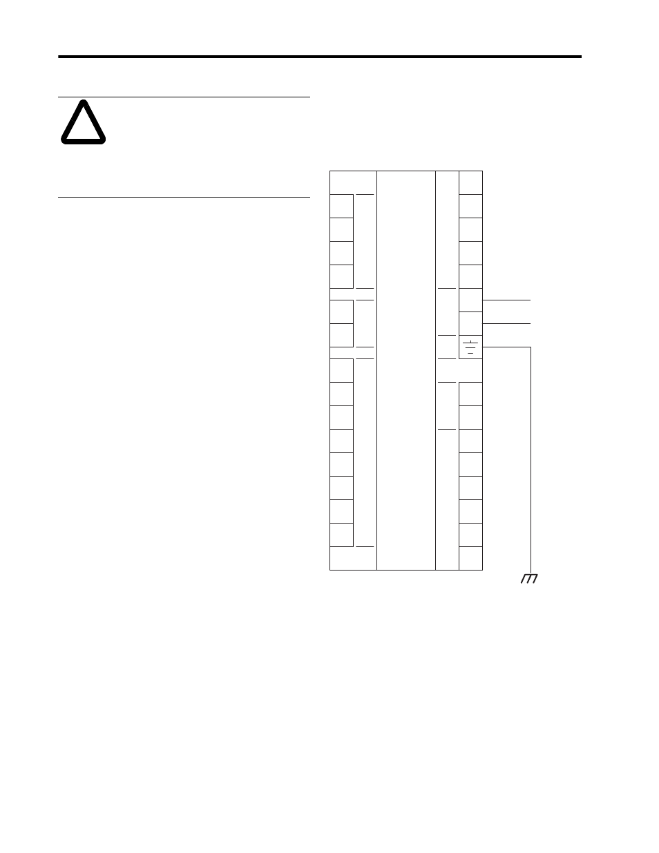
Figure 2.1 Bulletin 1403-XMXX
Voltage and Current Inputs
Voltage Input and Potential Transformer (PT) Selection
All Bulletin 1403-xM Powermonitor II devices
handle direct connection for line to neutral voltages
of 120, 277, and 347 (line to line voltages of 208,
480, and 600V, respectively).
!
ATTENTION: Failure to comply
with these mounting requirements
may cause damage to the Display
Module or compromise the IP65
[NEMA/UL 508, Type 4X (Indoor)]
degree of protection per International
Standard IEC 529.
V1
V2
V3
N
Fiber
Rx
Fiber
Tx
I1+
I2+
I3+
I4+
S1
S2
S3
S4
Scom
L/+
R14
R11
R12
R24
R21
R22
Acom
Ain
Cat. No. 1403-xMXXA
120/240 AC 50/60 HZ
125/250 DC
Cat. No. 1403-xMXXB
24 AC 50/60 HZ
12/24 DC
Voltage
Inputs
Status
Inputs
Display
Module
Fiber
Power
GRD
N/-
PM-II
Master
Module
L1
N/L2
Analog
Input
Current
Inputs
I1-
I2-
I3-
I4-
Relay
Outputs
Local Frame
Ground