Quick start - minimum device configuration, Measurements, Displays – Rockwell Automation 1403-DM_LM_MM Powermonitor II Instruction Sheet User Manual
Page 10
1-2
Product Description
1403-IN001A-US-P
Quick Start - Minimum Device Configuration
At a minimum, the following steps MUST be
followed for proper operation of your Powermonitor
II. Any other device configuration options are only
required for operation of additional functions of the
Powermonitor II.
1. Configure the PT and CT ratios to match your
system. Remember, for systems with greater than
120 volts applied to the voltage inputs, the PT
secondary must be configured to greater than 137
volts to switch to high voltage mode. For
example: a 600 V
L-L
(347 V
L-N
) direct-connect
system is configured with a PT ratio of 347:347.
2. Configure the Voltage Mode to match your system
wiring. Use the wiring diagrams in Chapter 2,
Figure 2.2 through Figure 2.13 to select the
appropriate mode.
Measurements
The Powermonitor II provides numerous display
measurements and programming characteristics.
Note:
Update rates and accuracy are listed in
Appendix C, Technical Specifications
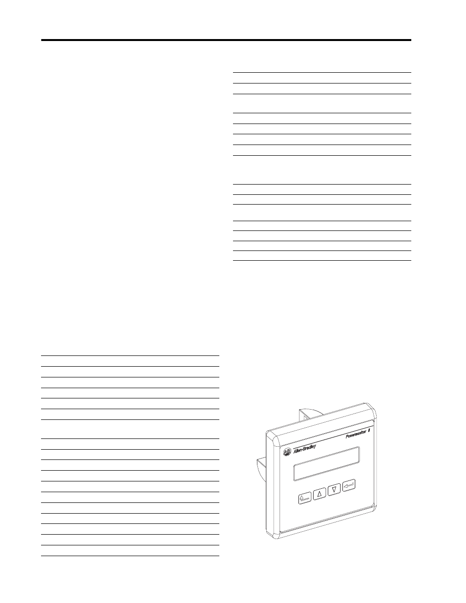
Displays
The Powermonitor II Master Module communicates
to the Display Module over a fiber optic serial
communications link. Up to three Display Modules
can connect to one Master Module.
Figure 1.1 Display Module
Table 1.1 Real Time Metering Measurements
Current in Amps (per phase and neutral)
Average Current in Amps
Positive Sequence Current in Amps
Negative Sequence Current in Amps
Percent Current Unbalance
Voltage in Volts (per phase L-L, and L-N on 4-wire systems)
Average Voltage in Volts (per phase L-L, and L-N on 4-wire
systems)
VAUX (auxiliary voltage input)
Positive Sequence Volts in Volts
Negative Sequence Volts in Volts
Percent Voltage Unbalance
Frequency in Hz
Phase Rotation (ABC, ACB)
Watts (total, and per phase on 4-wire systems)
VAR (total, and per phase on 4-wire systems)
VA (total, and per phase on 4-wire systems)
True PF (total, and per phase on 4-wire systems)
Displacement PF (total, and per phase on 4-wire systems)
Distortion PF (total, and per phase on 4-wire systems)
Power Consumption in kW Hours (forward, reverse, and net)
Reactive Power Consumption in kVAR Hours (forward, reverse,
and net)
Demand (Amps, Watts, VAR, and VA)
Instantaneous Demand (Amps, Watts, VAR, and VA)
First Order Projected Demand (Amps, Watts, VAR, and VA)
Second Order Projected Demand (Amps, Watts, VAR, and VA)
Table 1.2 Real Time Harmonic Analysis (V1, V2, V3, I1, I2, I3,
and neutral)
Percent Distortion up to 41st Harmonic (1403-MM only)
IEEE Percent Total Harmonic Distortion
IEC Percent Total Harmonic Distortion (Distortion Index)
(DIN)
IEEE-519 Compliance (1403-MM only)
Telephone Interference Factor (1403-MM only)
Crest Factor (1403-MM only)
K-Factor (1403-MM only)
Table 1.1 Real Time Metering Measurements