Power – Rockwell Automation 1403-DM_LM_MM Powermonitor II Instruction Sheet User Manual
Page 48
4-12
General Operation
1403-IN001A-US-P
Power
Table 4.5 displays the Power Metering information
provided by the Powermonitor II. The gray scale
indicates which parameters are available through the
Display Module, the Smart Communication Card, or
both.
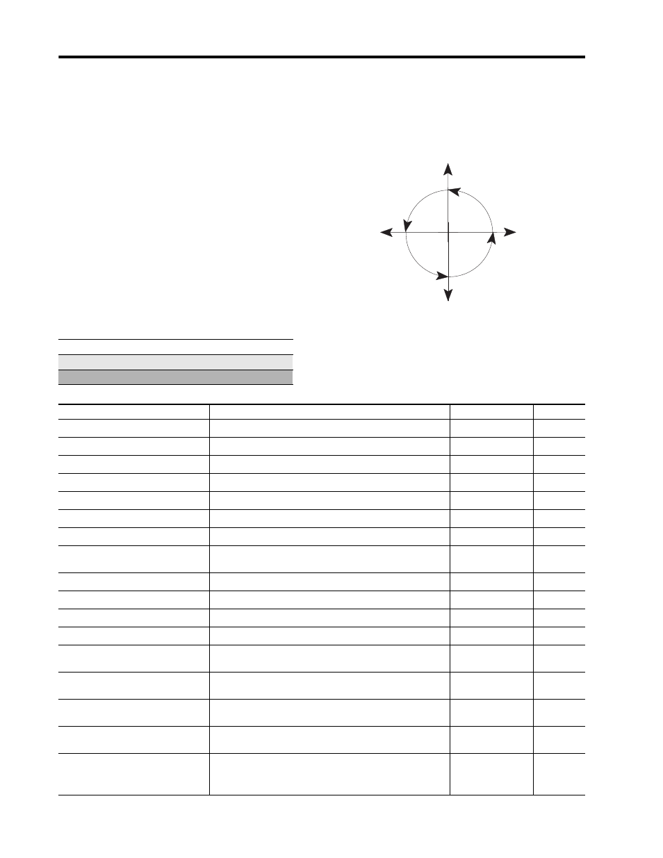
The power quantities (kW, kWH, kVAR, kVARH,
and power factor) measured by the Powermonitor II
are four-quadrant measurements. This allows the user
to individually determine the magnitude and
direction of both the real power flow and the reactive
power flow. Figure 4.3 indicates the relationship
between these quantities and the numeric signs used
by the Powermonitor II to convey the information.
Figure 4.3 Power Metering
Display Module and Smart Communication Card
Display Module Only
Smart Communication Card Only
I
IV
II
III
Pf = 1
+kVAR (Import)
kVARHR-F (Forward)
90°
Pf = 0
-kVAR (Export)
kVARHR-R(Reverse)
270°
Pf = 100%
+kW (Import)
kWH-F
(Forward)
0°
Pf = 100%
-kW(Export)
kWH-R
(Reverse)
180°
(Power Factor
Lagging)
(-)
(Power Factor
Lagging)
(-)
(Power Factor
Leading)
(+)
(Power Factor
Leading)
(+)
Table 4.5 Power Metering
Parameter
Description
Range
Units
Phase 1 Power
Power of phase 1 signed to show direction.
0 to 999.9x10
22
Watts
Phase 2 Power
Power of phase 2 signed to show direction.
0 to 999.9x10
22
Watts
Phase 3 Power
Power of phase 3 signed to show direction.
0 to 999.9x10
22
Watts
3-Phase Total Power
Total power of phase 1, 2, and 3 signed to show direction.
0 to 999.9x10
22
Watts
Phase 1 Reactive Power
Reactive power of phase 1 signed to show direction.
0 to 999.9x10
22
Vars
Phase 2 Reactive Power
Reactive power of phase 2 signed to show direction.
0 to 999.9x10
22
Vars
Phase 3 Reactive Power
Reactive power of phase 3 signed to show direction.
0 to 999.9x10
22
Vars
3-Phase Total Reactive Power
Total reactive power of phase 1, 2, and 3 signed to show
direction.
0 to 999.9x10
22
Vars
Phase 1 Apparent Power
Apparent power of phase 1.
0 to 999.9x10
22
VA
Phase 2 Apparent Power
Apparent power of phase 2.
0 to 999.9x10
22
VA
Phase 3 Apparent Power
Apparent power of phase 3.
0 to 999.9x10
22
VA
3-Phase Total Apparent Power
Total apparent power of phase 1, 2, and 3.
0 to 999.9x10
22
VA
Phase 1 True Power Factor
The ratio between the power and apparent power for phase
1; this value is signed to show lead (+) or lag (-).
-100 to 100
Percent
Phase 2 True Power Factor
The ratio between the power and apparent power for phase
2; this value is signed to show lead (+) or lag (-).
-100 to 100
Percent
Phase 3 True Power Factor
The ratio between the power and apparent power for phase
3; this value is signed to show lead (+) or lag (-).
-100 to 100
Percent
Total True Power Factor
The ratio between the power and apparent power for phase
1, 2, and 3; this value is signed to show lead (+) or lag (-).
-100 to 100
Percent
Phase 1 Distortion Power Factor
The ratio between the magnitude of the fundamental and the
sum of the magnitudes for all of the current harmonics for
phase 1.
(1)
0 to 100
Percent