Wiring of display module – Rockwell Automation 1403-DM_LM_MM Powermonitor II Instruction Sheet User Manual
Page 30
2-18
Installation
1403-IN001A-US-P
Wiring of Display Module
Note:
All ground wires should be kept as short as
possible; 30cm (12 in.) or less is suggested.
Power
The Display Module can be operated on either AC or
DC power. Two models have been developed to
operate on various AC/DC voltage ranges as defined
in Table 2.4. A single, three-position connector is
provided for all power connections to the Display
Module.
Terminal Block Wire Sizes and Screw Torque
Values
All terminal block wire sizes and terminal block
screw torque values are shown in Appendix C,
Technical Specifications .
Fiber Optics
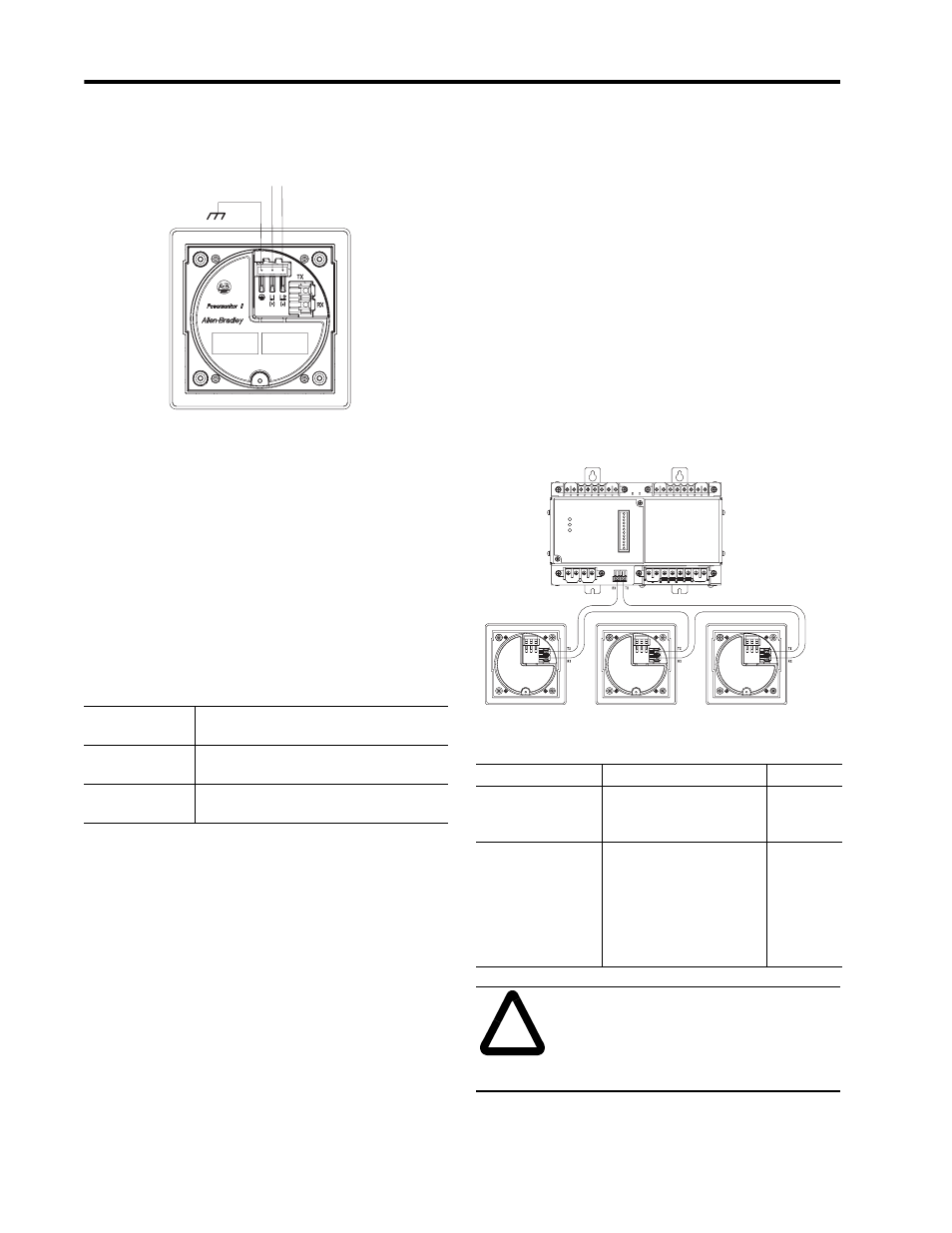
The Powermonitor II communications architecture
consists of a fiber optic ring between the Bulletin
1403 Master Module and up to three Display
Modules. The black transmitter component (TX) of a
unit must be connected to the blue receiver (RX)
component of the next unit and repeated for each
additional module until the ring is completed. Figure
2.17 shows a typical layout of the fiber optic cabling
between one Master Module and three Display
Modules. Fiber optic cable assembly specifications
are given in Table 2.5 on page 2-18.
Important: Always maintain furnished rubber plugs
in the transmitter and receiver when
cable end connectors are not in place.
This helps prevent dirt from
contaminating the transmitter or
receiver.
Figure 2.17 Fiber Optic Communications between a Bulletin
1403 Master Module and Three Display Modules
Table 2.4 Display Module Voltage Ratings
Cat. No./
Voltage Range
AC Voltages/DC Voltages
(+10% to -20%)
1403-DMA/High
Voltage
120 VAC, 240 VAC / 125 VDC, 250 VDC
1403-DMB/Low
Voltage
12 VAC, 24 VAC / 12 VDC, 24 VDC, 48 VDC
L1/+ L1/-
Local Frame Ground
Table 2.5 Fiber Optic Cable Assembly Specifications
Parameter
Minimum
Maximum
Cable Length:
Distance between
two adjacent devices
25 cm (approx. 10 in.)
shortest Allen-Bradley
standard
500 m
(1650 ft.)
Minimum inside bend
radius
25.4mm (1 in.) Any bends
with a shorter inside radius
can permanently damage
the fiber optic cable. Signal
attentuation increases with
decreased inside bend
radii.
N/A
!
ATTENTION: Any bend in a fiber
optic cable assembly with an inside
radius of less than 25.4 mm (1 in.)
may permanently damage the fiber
optic cable assembly.