Harmonic analysis – Rockwell Automation 1403-DM_LM_MM Powermonitor II Instruction Sheet User Manual
Page 51
General Operation
4-15
1403-IN001A-US-P
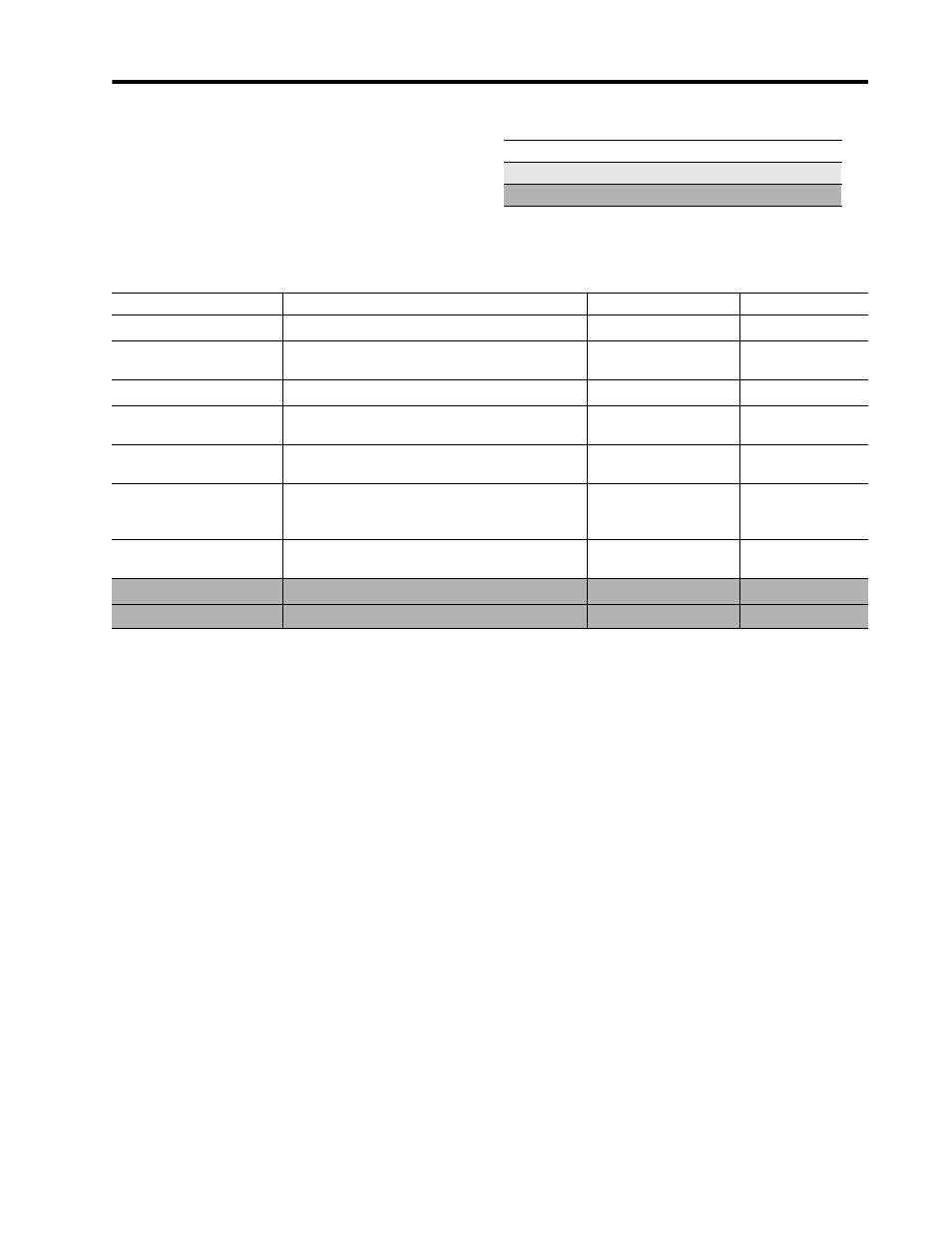
Harmonic Analysis
Table 4.7 displays the Harmonic Analysis
information provided by the Powermonitor II. The
gray scale indicates which parameters are available
through the Display Module, the Smart
Communication Card, or both.
Display Module and Smart Communication Card
Display Module Only
Smart Communication Card Only
Table 4.7 Harmonic Analysis (V1, V2, V3, V4, I1, I2, I3, I4)
Parameter
Description
Range
Units
K-factor
(1)
Transformer heat ratio.
0 to 999.9x10
22
N/A
Crest Factor
1
Ratio of the peak amplitude to the RMS value; also
known as amplitude factor or peak factor.
0 to 999.9x10
22
N/A
TIF
1
Telephone influence factor.
0 to 999.9x10
22
N/A
IEEE-519 Compliance
1
Pass/fail indication of harmonic content per the IEEE-
519 specification.
OK
Fail
N/A
IEEE Total Harmonic
Distortion
Magnitude of measured harmonics with respect to
the fundamental.
0 - 1000
Percent
IEC Total Harmonic
Distortion
Magnitude of all measured harmonics excluding the
fundamental with respect to all measured harmonics
including the fundamental.
0 - 1000
Percent
Harmonic Distortion
1
Magnitude of each individual harmonic with respect
to the fundamental up to the 41st harmonic.
0 - 1000
Percent
Harmonic Magnitude
1
Magnitude of each harmonic up to the 41st.
0 to 999.9x10
22
Volts or Amps
Harmonic Phase Angle
1
Phase angle of each harmonic up to the 41st.
0 - 360
Degrees
(1) Available on 1403-MM only.