Table 3.p, Table 3.q – Rockwell Automation 825 Smart Motor Manager User Manual User Manual
Page 62
3-29 Functions
Publication 825-UM001B-EN-P January 2001
Application
•
High-voltage motors
•
Installations in a difficult environment, with moisture, dust, etc. (e.g., mines, gravel
pits, cement factory, mills, woodworking shops, water pumping stations, waste water
treatment)
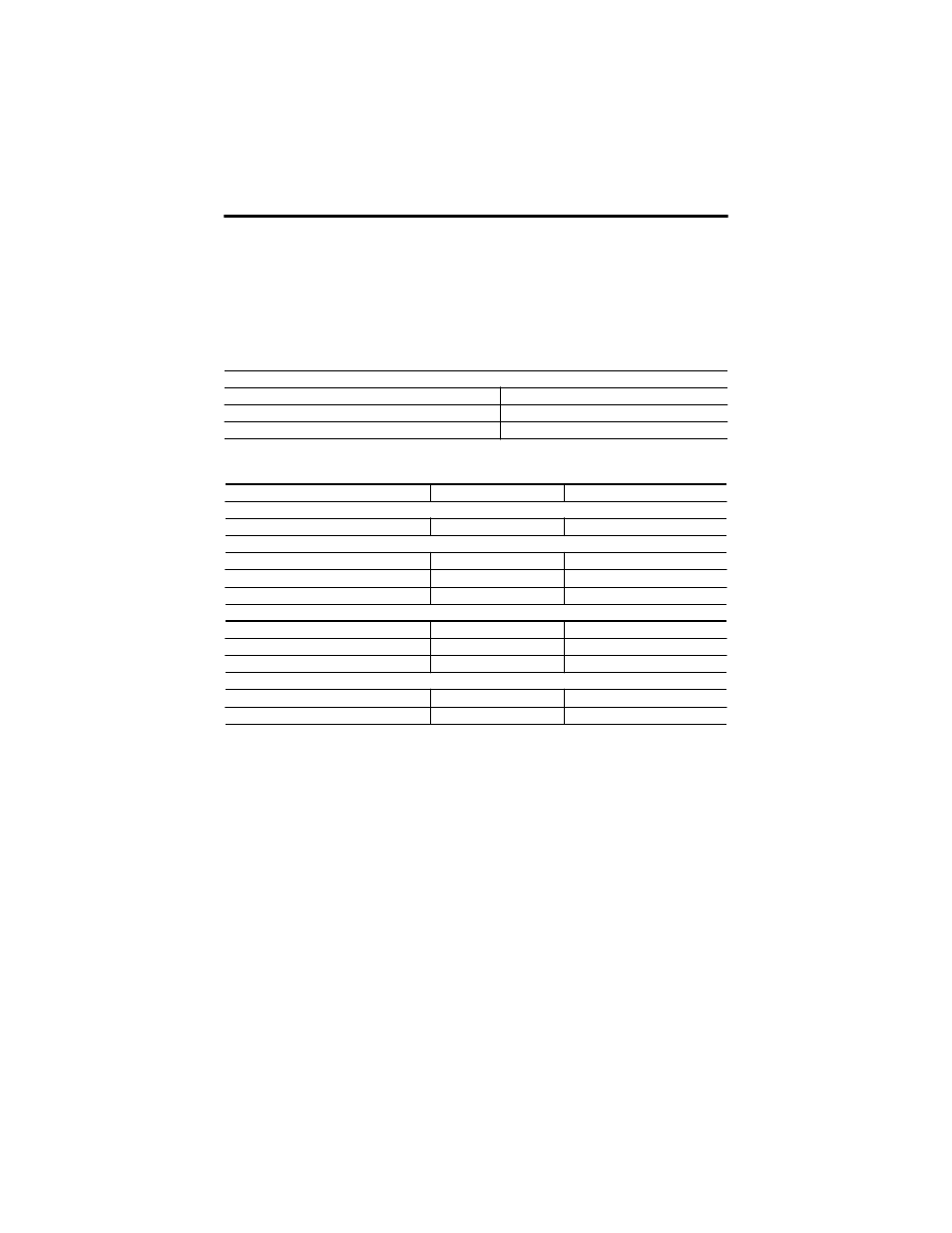
Table 3.P Core Balance Current Transformer Setting Parameters
Table 3.Q Earth (Ground) Fault Core Balance Setting Parameters
➊ –5…60
°
C (23…140
°
F)
➋ If auxiliary relays #2 and #3 are assigned to the communication (refer to page
) they cannot be selected
here.
Earth (Ground) Fault Protection in High-Voltage Systems
This section provides an overview of earth (ground) faults in isolated, high-impedance earth,
or compensated networks.
With earth neutral point-type networks, the magnitude of the earth (ground) fault (leak)
current is determined by the earth capacitance of the network and the earth resistance or the
compensating reactor. Because the size of industrial networks is limited, earth fault currents
are very small. To a great extent, earth capacitances are determined by the cables and the
motors.
The capacitance values for cables are given in cable tables and range from approximately
0.2…1.2
µ
F/km. A value between 0.02…0.05
µ
F per MW of motor rating can be assumed
for high-voltage motors.
Current Ratio
Setting range
1…2 000
Factory setting
100
Setting steps
1
Warning ➊
Trip ➊
Function
Factory setting
Off
On
Response Level
Setting range
5 mA…50 A
5 mA…50 A
Factory setting
500 mA
1.0 mA
Setting increments
5 mA
0.25 A
Tripping Delay
Setting range
—
0.1…5 s ± 0.04 s
Factory setting
—
0.5 s
Setting increments
—
0.1 s
Output Relay ➋
Selection (relays)
AL, #1…#5
MR, AL, #1…#5
Factory setting
AL
MR