Rockwell Automation 825 Smart Motor Manager User Manual User Manual
Page 136
8-4 Error Diagnosis and Troubleshooting
Publication 825-UM001B-EN-P January 2001
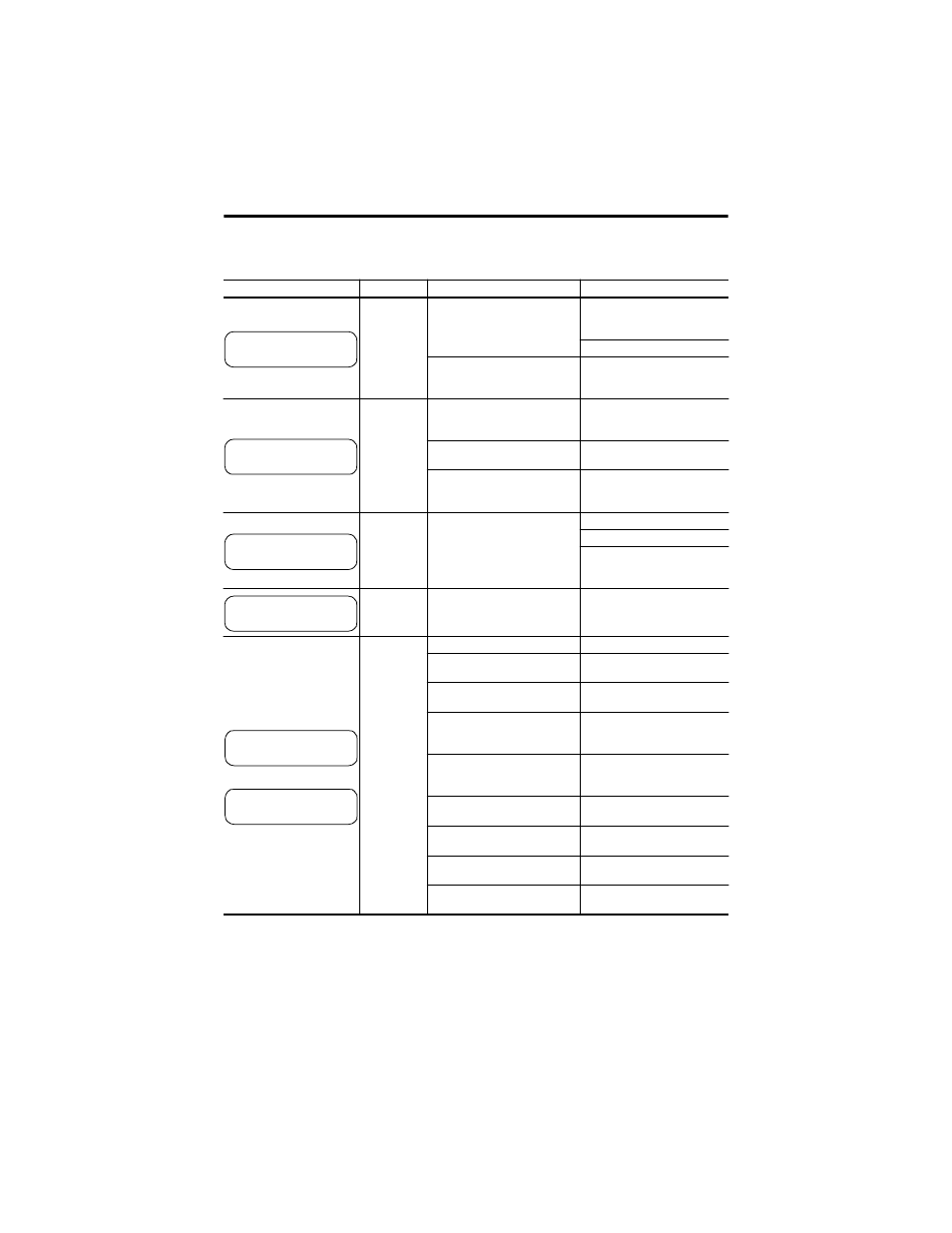
Table 8.A Possible Causes and Actions (Continued)
LCD
Designation
Possible Causes
Actions
Converter
module cannot
be correctly
recognized
Link between basic unit and
converter module defective
Check link between basic unit
and converter module and
replace if necessary.
Switch supply off and on again
Fault in basic unit
If the fault cannot be remedied,
send the unit back to the factory
for repair.
Rated current
and setting do
not agree
Converter module rated current
does not agree with basic unit
setting
Check setting “FULL LOAD
CURR” and converter module.
Wrong converter module
Install the correct converter
module
Wrong setting
Press “Values” until “SET
Values” on LCD, correct “FULL
LOAD CURR” (within about 5 s)
Error in actual
values
Data could not be saved when
supply last interrupted
Press Reset.
Check power supply.
If the fault repeatedly occurs,
send the unit back to the factory
for repair.
—
Hardware fault
Send the basic unit back to the
factory for repair.
Thermal
warning
Thermal trip
Overloaded
Reduce load.
Transported material jammed
Switch off installation, remedy
trouble.
Mechanical damage,
bearings, etc.
Repair the damage.
Settings of rated current or
tripping time too low
Raise “FULL LOAD
CURR”/”LOCKED ROT TIME” to
permissible motor values.
Interrupted start: motor
inadequately cooled
Wait until motor has cooled
down. (LCD: TH UTIL…% appr.
20%)
More than one warm start/hour
If permissible, increase
number of warm starts/h.
Ambient temperature too high
(Function PT100, #7 ON)
If possible, reduce load.
Very high third harmonic
(e.g., star-delta connection)
Raise
,
e
setting accordingly.
Cooling constant ratio has been
changed
Check and reset to correct
setting (factory setting 2.5).
825-MCM ERROR
IE OUT OF RANGE
ERROR ACT VALUES
ERROR REC VALUES
THERMAL WARNING
THERMAL TRIP