Fault codes, Table 8.a, Possible causes and actions – Rockwell Automation 825 Smart Motor Manager User Manual User Manual
Page 135
Error Diagnosis and Troubleshooting 8-3
Publication 825-UM001B-EN-P January 2001
Actions
Determine the trip cause and correct the problem before re-starting the motor installation.
Fault Codes
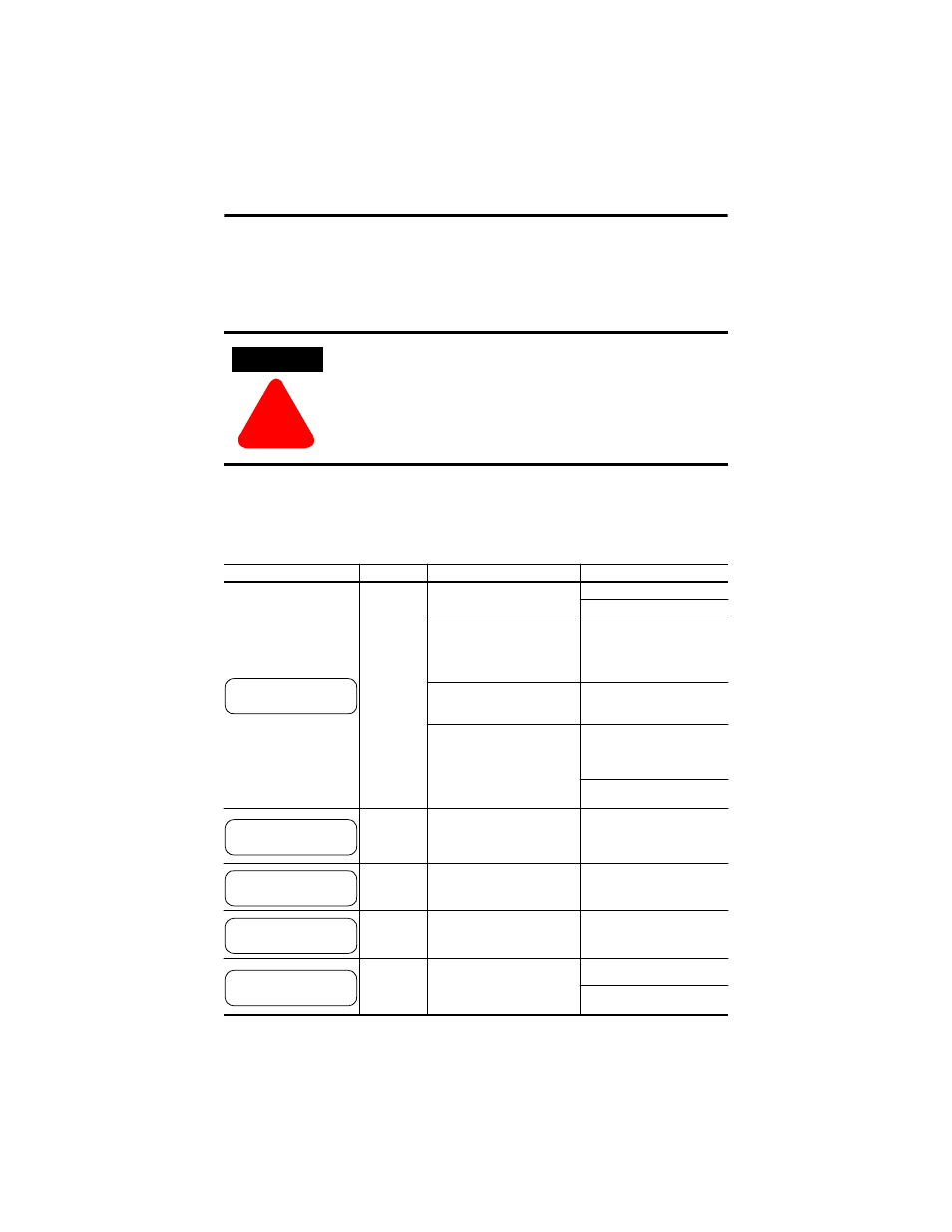
Table 8.A Possible Causes and Actions
ATTENTION
!
While the trip is on (red LED on), the protection function cannot be
disabled (refer to page
).
LCD
Designation
Possible Causes
Actions
No indication
No supply voltage
Ensure power supply is on.
Check the supply.
Wrong supply module
in basic unit
Insert correct supply module. If
the voltage applied to the supply
module was too high, it and the
functions of the unit must be
tested.
Basic unit defective
If no fault is found or if in doubt,
send the unit back to the factory
for repair.
Thermal trip of supply module
•
Supply voltage too high
•
Ambient temp. too high
•
Current consumption too high
•
Supply module failed
Switch off control supply.
Restore normal conditions and
let the unit cool down for
approx. 30 min.
Send the unit back to the factory
for repair.
V2.17
and later:
No indication,
red LED on
Watch Dog Microprocessor
failure
Send the basic unit back to the
factory for repair.
Real time
clock fault
RTC defective
Send the basic unit back to the
factory for repair.
µ
P fault
(RAM)
Microprocessor RAM defective
Send the basic unit back to the
factory for repair.
Open circuit
basic unit to
converter
module
Cable from basic unit to converter
module not connected or broken
Check connections.
Test cable (open/short-circuit).
Replace cable if necessary.
DEFECT #1
DEFECT #2
825-MCM NOT CON