Rockwell Automation 160 SER A FRN 1.XX-4.XX User Manual
Page 26
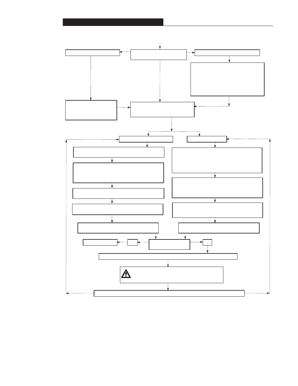
Chapter 4 - Start-Up
4–2
Reconnect the power to the
controller.
P01- [Output Frequency] will display. If the
controller has been previously powered up, a
different parameter number may display.
Note: To enable the start and reverse keys
from the program keypad module, set P46 -
[Input Mode] to a 2" and cycle power. Refer
to the programming example in Chapter 5.
If you have a program keypad module.
Do you have a Analog Signal
Follower controller or a Preset Speed
controller?
Analog Signal Follower controller
Preset Speed controller
Check for proper motor rotation by selecting P61 -
[Preset Frequency 0]. This requires removing all inputs
to SW1, SW2, and SW3 on TB3 [see Figure 2.5 in
Chapter 2]. The factory default setting for P61 - [Preset
Frequency 0] is 3 Hz.
If you have a blank display panel.
The READY [green] indicator
will illuminate. Use remote
inputs to TB3 control terminal
block to operate the controller.
Check for proper motor rotation by setting the frequency
source to its minimum setting.
If you are using a program keypad module, verify that the
CLOCKWISE LED is illuminated. If you are using a blank
display panel, verify that the REVERSE input to TB3 is in
the OPEN position.
Slowly increase the speed until the motor begins to turn.
Check the direction of the motor.
Is the direction of motor
rotation correct?
Yes
No
Startup is complete.
Disconnect and lock out all incoming power to TB1 terminals L1, L2, and L3 [R, S and T].
Issue a STOP command from either the program
keypad module or TB3 control block terminal.
If you are using a program keypad module, verify that the
CLOCKWISE LED is illuminated. If you are using a blank
display panel, verify that the REVERSE input to TB3 is in
the OPEN position.
Issue a START command from either the program keypad
module or TB3 control terminal block.
Issue a START command from either the program
keypad module or TB3 control terminal block. Check the
direction of motor rotation.
Issue a STOP command from either the program
keypad module or TB3 control block terminal.
ATTENTION:
A DC Bus voltage may be present at the
power terminal blocks (TB1) and (TB2) for approximately
one minute after power is removed from the controller.
Switch any two of the three motor leads connected to TB2, terminals T1, T2 and T3 [U, V and W].
A