Chapter 4 - start-up, Start-up procedure (analog signal follower model), Start-up procedure (preset speed model) – Rockwell Automation 160 SER A FRN 1.XX-4.XX User Manual
Page 25: Start–up procedure (analog signal follower model), Start–up procedure (preset speed model), Start-up, Chapter
4
Chapter
Start-Up
4–1
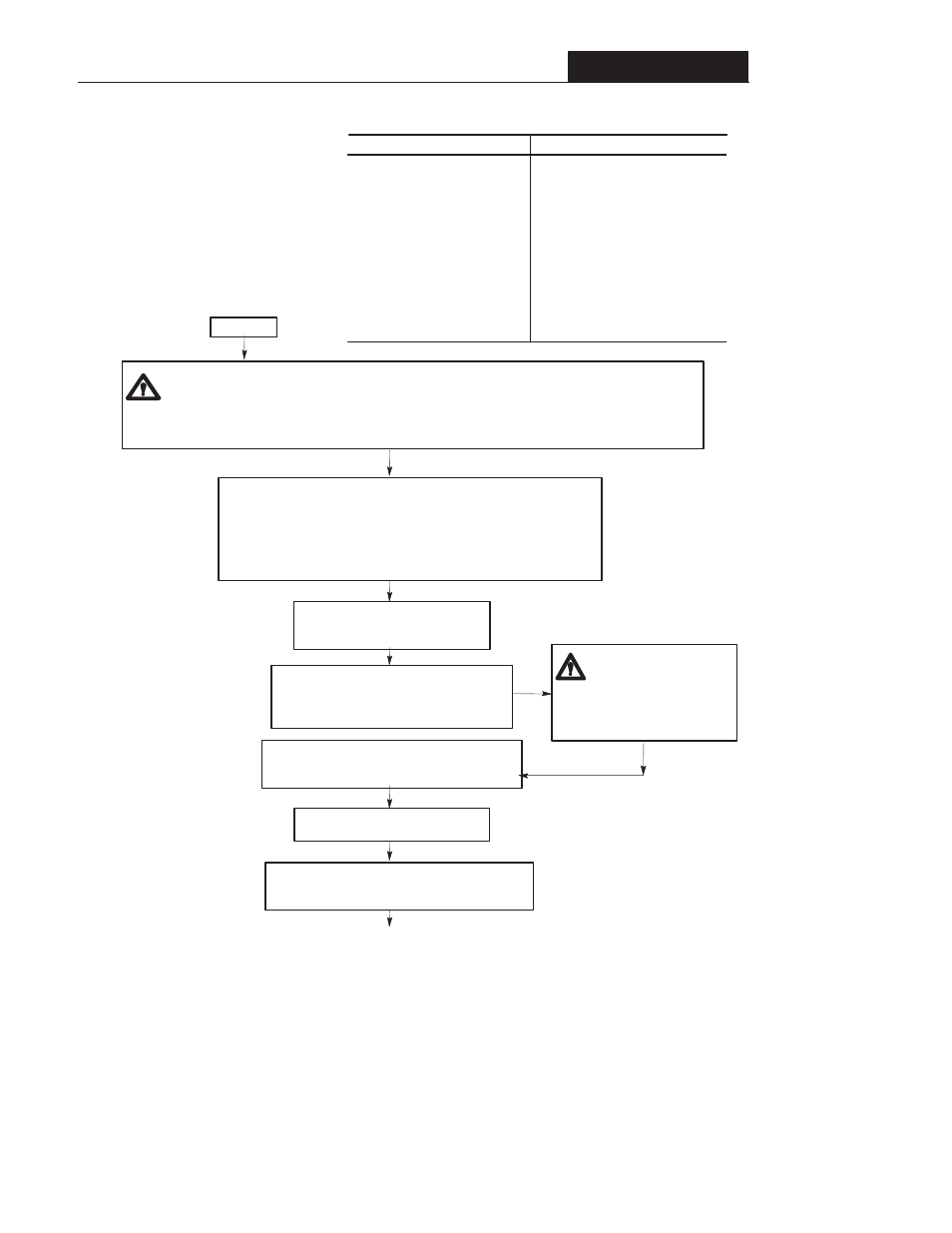
Verify that AC line power at the
disconnect device is within the rated
value of the controller.
Disconnect and lock out all incoming power to
the controller including incoming AC power to
terminals L1, L2 and L3 (R, S and T) of power
terminal block TB1.
Verify that the motor leads are connected to the
power terminal block TB2, terminals T1, T2, T3 (U,
V, W).
Verify that the STOP input is present
at the TB3 control terminal block.
Confirm that all other control inputs are connected to
the correct terminals and are secure. GO TO THE
NEXT PAGE.
ATTENTION:
A DC Bus
voltage may be present at the
power terminal blocks (TB1)
and (TB2) for approximately
one minute after power is
removed from the controller.
D
Minimum clearance distance between controller and other equipment.
D
Proper grounding practices have been followed.
D
Proper power and control wiring has been used.
Start-Up Checklist
Verify the controller is installed per instructions outlined in Chapter 2 including:
P30-[Accel Time 1]
P31-[Decel Time 1]
P33-[Maximum Frequency]
P34-[Stop Mode Select]
P35-[Base Frequency]
P36-[Base Voltage]
P42-[Motor Overload Current]
P46-[Input Mode]
P47-[Output Configure]
Preset Speed Model Only
P61-P68-[Preset Frequency 0-7]
Chapter 5 provides a comprehensive description of
all controller parameters. Review the factory default
settings. If your controller is equipped with a ProĆ
gram Keypad Module these parameters can be
changed to meet your specific application requireĆ
ments. An example of how to program a parameter
is shown at the beginning of Chapter 5.
ATTENTION:
Power must be applied to the controller to perform the following startĆup procedure. Some of
the voltages present are at incoming line potential. To avoid electric shock hazard or damage to equipment, only
qualified service personnel should perform the following procedure. Thoroughly read and understand the
procedure before beginning. If an event does not occur while performing this procedure, Do Not Proceed.
Remove Power by opening the branch circuit disconnect device and correct the malfunction before continuing.
desired accel time.
desired decel time.
maximum frequency required.
desired stopping mode.
motors rated nameplate frequency.
motors rated nameplate voltage.
motor nameplate Full Load Amps [FLA].
desired control method.
desired output functionality.
desired preset frequencies.
Parameter
Set to...
Commonly Changed Parameters
Start Here
A