Chapter 2 - installation and wiring, Installation and storage, Emc directive 89/ 336/ eec compliance – Rockwell Automation 160 SER A FRN 1.XX-4.XX User Manual
Page 15: Emc directive 89/336/eec compliance, Installation and wiring
2
Chapter
Installation and Wiring
2–1
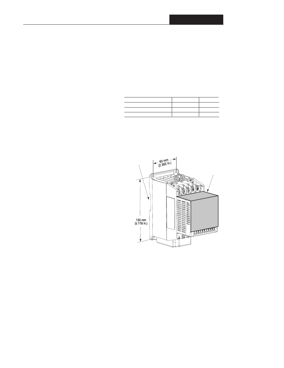
Figure 2.1 - Mounting Requirements
Note:There must be a minimum of 12.5mm
(0.5 inches) clearance around all sides of the controller. Use
either DIN rail or mounting holes.
À
Debris Cover
Б
Б
Leave debris cover attached during controller installation to
protect from falling debris. To ensure proper controller
operation, remove cover before applying power.
DIN Mounting
À
Use the drilling template at the back of the manual for
mounting the controller.
This product complies with Electromagnetic
Compatibility (EMC) Directive 89/336/EEC, when
the following requirements for a conforming
installation are applied:
D an input line filter must be installed to reduce
conducted emissions. Refer to the accessory
list in Appendix A.
D the controller system must be mounted in a
shielded enclosure to reduce radiated
emissions. A typical NEMA or IEC metal
enclosure is adequate.
D motor cables must be in conduit, or have
shielding/armor with equivalent attenuation to
reduce radiated emissions.
D motor cable lengths are as specified in table
2.A.
D control and signal wiring must be in conduit or
have shielding with equivalent attenuation.
EMC Directive 89/336/EEC Compliance
Min. Panel Thickness (14 GA)
Mounting Base Screws
Mounting Torque
Description
.0747 in.
# 8-32
10-14 lb. in.
English
1.9 mm
m4 x 0.7
1.13 to 1.56 Nm.
Metric
Note: See Appendix A for details on controller dimensions
and weights.
Installation and Storage
Take these actions to prolong controller life and
performance:
D store within an ambient temperature range of
-40
_ to +85_C
D store within a relative humidity range of 0%
to 95%, non–condensing
D protect the cooling fan by avoiding dust or
metallic particles
D avoid storing or operating the controller
where it could be exposed to a corrosive
atmosphere
D protect from moisture and direct sunlight
D operate at an ambient temperature range of
0
_ to +50_C
To maintain proper working conditions, install
the controller on a flat, vertical and level
surface. Use mounting screws up to 4.5mm
(0.177 inches) in diameter or mount on 35mm
DIN Rail.
Important: The conformity of this controller and
filter to any standard does not guarantee that the
entire installation will conform. Many factors can
influence the total installation and only direct
measurements can verify total conformity.
A copy of the Declaration of Conformity (DOC) is
available from your local Allen–Bradley sales
office.