Controller features – Rockwell Automation 160 SER A FRN 1.XX-4.XX User Manual
Page 16
Chapter 2 - Installation/Wiring
2–2
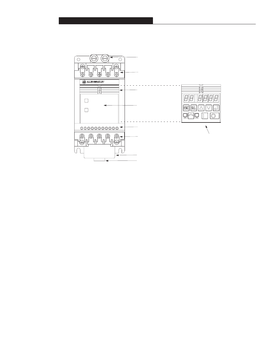
Ground Tab
Terminal Block One
(TB1) - For Line Power.
Terminal Block Three (TB3)
- For Control Wiring.
Terminal Block Two (TB2)
- For Motor Wiring.
Ready/Fault Indicating
Panel - Standard for
Bulletin 160 controllers.
Program Keypad Module - This can be
ordered separately, Catalog 160-P1, or
as a factory-installed option by adding
P1" to the end of the catalog number.
Refer to Chapter 3, Program Keypad
Module for a detailed explanation of
functionality.
Fan
LEDs - Indicate
operational status.
FAULT
8
7
6
5
4
3
2
1
9 1
10 1
READY
S
T
-
L3
L2
L1
BR
+
R
T1
T2
T3
+
V
DC DC
-
U
W
Figure 2.2 - Controller Features
Controller Features
Figure 2.2 above details the features of both the
Analog Signal Follower and Preset Speed
models.
Note: The features are the same for single and
three phase units.
Controller Operation Without a Program
Keypad Module
Bulletin 160 controllers are fully functional
without the use of a program keypad module.
All control functions can be performed from the
control terminal block (TB3). A program
keypad module is required to change the factory
default parameter settings.
Diagnostics For Controllers Without a
Program Keypad Module
There are two indicators provided to display
the controller’s status condition.
The READY (green) indicator illuminates
when the DC bus is charged and the
controller is ready to run.
The FAULT (red) indicator illuminates
when a controller fault condition exists.
Refer to Chapter 6 for details on how to
clear a fault and general troubleshooting
procedures.
DIN Latch
BR