Original instructions, 4 errors displayed by the 7-segment display – Rockwell Automation 442L SafeZone Singlezone & Multizone Safety Laser Scanner User Manual
Page 43
R
SafeZone™ Safety Laser Scanner User Manual
10000073050, July 2011 41
Original instructions
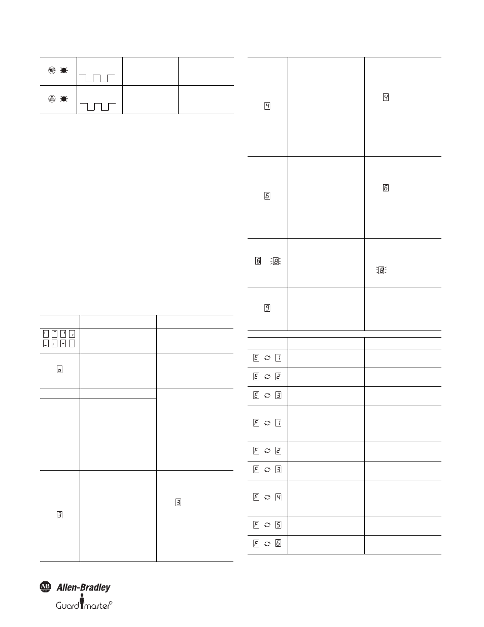
10.4 Errors displayed by the 7-segment
display
This section explains the meaning of the error displays on the 7-segment
display and how to respond to the messages. You will find a description
of the positions and symbols on the SafeZone multizone safety laser
scanner in Section 3.5 “Indicators and outputs” on page 17.
Application
diagnostic output
Front screen
contaminated, still in
operation
² Clean the front screen.
At the Res_Req
output
Reset required
² Operate the control
switch for restarting
or resetting.
Display
Possible Cause
Remedying the Error
Power-up cycle~all segments are
activated sequentially.
No error
Park mode (see Section “Park mode”
on page 16); the
OSSDs are deactivated, the laser is
shutdown.
No error. Readiness for operation is
restored by switching to
another monitoring case.
Object in protective safety field
No error. Status indication eases
system testing on the use of
simultaneous protective safety fields
or in master/slave operation (if the
OSSDs on the slave are not used in
master/slave operation, then as
required in the standard, a protective
safety field infringement is not
signalled via the red LED on the
slave).
Object in the simultaneous protective
safety field
or
the contour as reference function has
triggered
Initializing the device
² The display goes off automatically
when the SafeZone safety laser
scanner is initialized
If display
does not go off:
² Check the cabling.
² Check the system configuration
with the aid of the SCD software.
Re-transfer the corrected
configuration to the SafeZone
safety laser scanner.
1 Hz
1 Hz
.
,
,
,
,
,
,
,
.
Waiting for valid input signal
² The display goes off automatically
when an input signal is present
that corresponds to a configured
monitoring case.
If display
does not go off:
² Check the cabling.
² Check the configuration of the
system using the SCD software.
Re-transfer the corrected
configuration to the SafeZone
safety laser scanner.
Waiting for configuration or
configuration not complete
² The display goes off automatically
once the configuration has been
successfully transferred.
If display
does not go off:
² Check the configuration of the
system using the SCD software.
Re-transfer the corrected
configuration to the SafeZone
safety laser scanner.
or
EDM error
² Check whether the contactors are
stuck or incorrectly wired and
rectify any error.
² If
is displayed: Switch the
device off and back on again.
Error in control switch for restarting
or resetting
² Check the functionality of the
control switch. The button may
be defective or stuck.
² Check the wiring of the control
switch for short-circuit to 24V.
Display
Possible Cause
Remedying the Error
Sensor head faulty
² Send the sensor head to the
manufacturer for repair.
I/O module faulty
² Send the I/O module to the
manufacturer for repair.
Configuration memory in the system
connector faulty
² Send the system connector to the
manufacturer for repair.
Overcurrent on OSSD connection 1
² Check the switching element
connected. Replace, if necessary.
² Check the wiring for short-circuit
to 0V.
Short-circuit to 24V at OSSD
connection 1
² Check the wiring for short-circuit
to 24V.
Short-circuit to 0V at OSSD
connection 1
² Check the wiring for short-circuit
to 0V.
Overcurrent on OSSD connection 2
² Check the switching element
connected. Replace, if necessary.
² Check the wiring for short-circuit
to 0V.
Short-circuit to 24V at OSSD
connection 2
² Check the wiring for short-circuit
to 24V.
Short-circuit to 0V at OSSD
connection 2
² Check the wiring for short-circuit
to 0V.
.
.
.
.
.
.
.
.
.
.
.
.
.
.
.
.
.
.
.
.