Original instructions – Rockwell Automation 442L SafeZone Singlezone & Multizone Safety Laser Scanner User Manual
Page 15
R
SafeZone™ Safety Laser Scanner User Manual
10000073050, July 2011 13
Original instructions
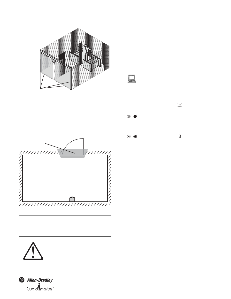
Figure 16: Protective safety field as reference for vertical operation
Horizontal operation
If the protective safety field reaches the walls of a room partially or
entirely, the SafeZone safety laser scanner can also monitor the contour
of the protective safety field. The OSSDs on the SafeZone multizone
safety laser scanner then change to the off status if the room contour
changes due the opening of a door, even if there is no object in the
protective safety field.
Figure 17: Protective safety field as reference for horizontal operation
3.4.4 External device monitoring (EDM)
The EDM function monitors the contact elements activated by both the
OSSDs (e.g. contactors). The machine is only allowed to start if both
contactors are in the de-energized state on reset, that is they are
deactivated.
The SafeZone safety laser scanner monitors the contactors after every
interruption of the protective safety field and before the restart of the
machine. The EDM can in this way identify if one of the contactors has
welded in the following manner.
3.4.5 Application diagnostic output
The application diagnostic output, when not configured, sources 24V
DC. When configured for contamination or status of outputs (OSSDs)
or both, the ADO will turn off to signal one of the configured states (see
Table 21 on page 40).
IMPORTANT
It is not possible to define any warning
field in the areas of the contour
segments. This is only possible
between contour segments.
ATTENTION
Each output signal switching device
(OSSD) is only allowed to be connected
to one switching element (e.g. relay or
contactor).
Contours on the floor and the
side walls as reference
Door as reference
You can configure the external device monitoring in
the SCD (device symbol SafeZone safety laser
scanner system, context menu Configuration draft,
Edit..., file card Scanner name).
• If no internal restart interlock is configured, then
- the system locks completely (lock-out).
- the error message
appears in the 7-
segment display.
• If an internal restart interlock is configured, then
- the SafeZone safety laser scanner
deactivates its OSSDs.
- the adjacent LED illuminates.
- the error message
appears in the 7-
segment display.
- with the flashing LED the SafeZone safety
laser scanner signals that the control
switch for restarting or resetting the
restart must be operated.
Notes
• You will find examples on the connection of the
external device monitoring in Section 6.3
“Example circuits” on page 34.
• If you do not use the external device monitoring
function, leave the inputs disconnected (see
Section 5.1.1 “Pin assignments of the I/O
modules” on page 32).
.
.