Original instructions, 5 adhesive label important information – Rockwell Automation 442L SafeZone Singlezone & Multizone Safety Laser Scanner User Manual
Page 32
R
SafeZone™ Safety Laser Scanner User Manual
30 10000073050, July 2011
Original instructions
² Mount kit 1 on the mounting surface.
² Mount the SafeZone safety laser scanner on mounting kit 1.
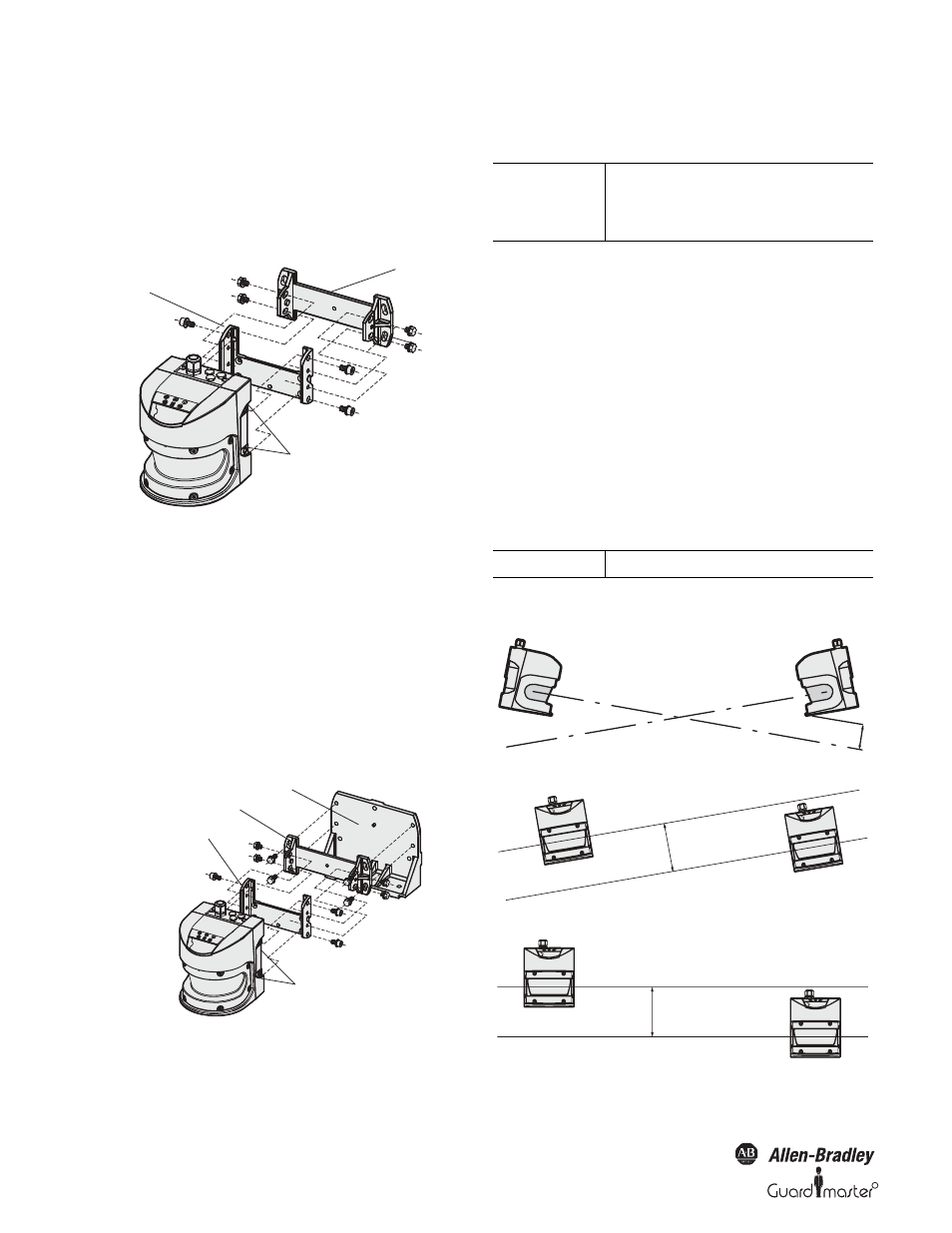
4.6.3 Mounting with mounting kit 2
With the aid of mounting kit 2 (only in conjunction with mounting kit 1)
you can align the SafeZone safety laser scanner in two planes. The
maximum adjustment angle is ±11° in both planes.
Figure 43: Mounting with mounting kit 2
² Mount kit 2 on the mounting surface.
² Mount kit 1 on mounting kit 2.
² Mount the SafeZone safety laser scanner on kit 1.
² Adjust the SafeZone safety laser scanner longitudinally and cross-wise.
4.6.4 Mounting with mounting kit 3
With the aid of mounting kit 3 (only in conjunction with mounting kits
1 and 2) you can mount the SafeZone multizone safety laser scanner such
that the scan plane is parallel to the mounting surface. This enables stable
floor mounting or ensures that mounting kit 2 remains precisely
adjustable cross-wise on uneven wall surfaces.
Figure 44: Mounting with mounting kit 3
² Mount kit 3 on the mounting surface.
² Mount kit 2 on kit 3.
² Mount kit 1 on kit 2.
² Finally mount the SafeZone safety laser scanner on mounting kit 1.
² Adjust the SafeZone safety laser scanner longitudinally and cross-wise.
4.6.5 Adhesive label Important information
² On completion of mounting, you must affix the self-adhesive label
Important information supplied with the SafeZone safety laser scanner:
- Use only the information label in the language which the
operators of the machine understand.
- Affix the label such that it is clearly visible for the users/
operators during operation. The label must not be
covered even after additional items have been mounted.
4.6.6 Using multiple SafeZone safety laser scanners
The SafeZone safety laser scanner is so designed that mutual interference
between several scanners is unlikely. To completely exclude erroneous
switching, you must mount the scanners as shown in the following
examples.
Use the mounting kits 1 to 3 to adjust the scanners to different angles
(see Section 12.2 “Accessories and replacement parts” on page 53).
Figure 45: Opposite mounting
Figure 46: Inclined, parallel mounting
Figure 47: Offset parallel mounting
Threaded mounting holes
M8 x 9
Mounting screws
for the sensor
Mounting kit 1
Mounting kit 2
Threaded Mounting holes
M8 x 9
Mounting kit 1
Mounting screw
for the sensor
Mounting kit 2
Mounting kit 3
IMPORTANT
During mounting, please observe the
dimensional drawings in “Technical
specifications” (see Section 11.5
“Dimensional drawings” on page 50).
IMPORTANT
In all circumstances observe EN 999.
100 mm
200 mm
200 mm