Original instructions, 3 indications and error messages – Rockwell Automation 442L SafeZone Singlezone & Multizone Safety Laser Scanner User Manual
Page 42
R
SafeZone™ Safety Laser Scanner User Manual
40 10000073050, July 2011
Original instructions
² If possible use anti-static floor mats and workbench covers.
² When working on the SafeZone safety laser scanner, touch a bare metal
surface from time to time to discharge static charging of your body.
² Only remove the components for the SafeZone safety laser scanner from
their anti-static packing immediately prior to installation.
² Note that no liability can be accepted for damage caused by electrostatic
discharge.
Replacing the I/O module:
² Disconnect the system connector and remove the SafeZone safety laser
scanner.
² Take the SafeZone safety laser scanner to a clean place (office, repair
shop or similar).
² First clean the outside of the SafeZone safety laser scanner.
This prevents foreign bodies entering the device when it is opened.
² Undo the mounting screws for the I/O module.
² Take hold of the I/O module with one hand at the recess for the
connector to the system connection.
² With the other hand take hold of the I/O module at the dismantling aid
on the underside of the device.
² Pull out the I/O module parallel to the mounting shaft.
² Remove any contamination from the sealing surface and the mating
surface for the sensor head. For this purpose if possible use a plastic
cleaner that does not leave residues (see Section 12.2 “Accessories/spare
parts” on page 53).
² Remove the I/O module from the packaging, ensure that you take
adequate ESD protection measures during this process.
² Check the surfaces for cleanliness and the seal for correct seating.
² Insert the I/O module in the mounting shaft parallel to the rear of the
sensor head. During this process use the three surrounding sides of the
shaft for orientation.
² Guide the I/O module along these surfaces to the connector. During
this process slide the I/O module parallel to the rear of the sensor, avoid
tilting. The I/O module can be connected without the need to apply
force.
² When the I/O module is flat against the rear of the sensor head
(distance approx. 1 N
•m or 8.9 in•lbf ), tighten the screws in stages,
diagonally (to 10…12 N
•m or 88.5…106 in•lbf).
Re-commissioning the SafeZone safety laser scanner:
² Correctly re-mount the SafeZone safety laser scanner (see Section 4
“Installation and mounting” on page 18).
² Connect the SafeZone safety laser scanner system connector.
After power up the SafeZone safety laser scanner
automatically reads the saved configuration from the
system connector (see Section 8.3 “Re-commissioning”
on page 37).
Section 10 — Diagnostics
This section describes how to identify and remedy errors and
malfunctions during the operation of the safety laser scanner.
10.1 In the event of faults or errors
10.2 Rockwell Automation Support
If you cannot remedy an error with the help of the information provided
in this section, please contact your local Rockwell representative or
technical support.
10.3 Indications and error messages
This section describes the meaning of the indications and error messages
and how you can respond. You will find a description of the indicators in
Section 3.5 “Indicators and outputs” on page 17, the connections for the
outputs in Section 5.1 “System connection” on page 31.
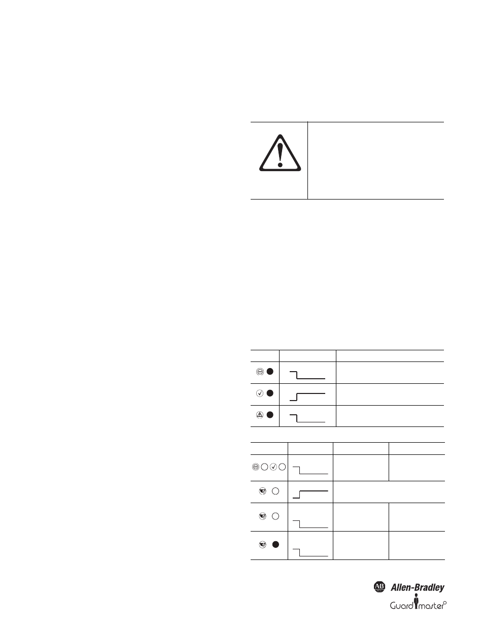
ATTENTION
If a fault or error is observed, cease
operation if the cause of the
malfunction has not been clearly
identified.
Stop the machine, the system or the
vehicle if you cannot clearly identify or
allocate the error and if you cannot
safely remedy the malfunction.
Display
Output Level
Possible Cause
At the OSSDs
Object in the protective safety field, OSSDs
deactivated
At the OSSDs
Protective safety field unoccupied, OSSDs activated
At the warning field output
Object in warning field
Display
Output Level
Possible Cause
Remedying the Error
OSSDs
No operating voltage, or
voltage too low
² Check the voltage
supply and activate, if
necessary.
Error/contamination
No error
Application
diagnostic output
No supply voltage
² Check the voltage
supply and activate, if
necessary.
Application
diagnostic output
Front screen
contaminated, operation
not
² Clean the front screen.