Original instructions – Rockwell Automation 442L SafeZone Singlezone & Multizone Safety Laser Scanner User Manual
Page 24
R
SafeZone™ Safety Laser Scanner User Manual
22 10000073050, July 2011
Original instructions
Table 10: Size of the unprotected areas
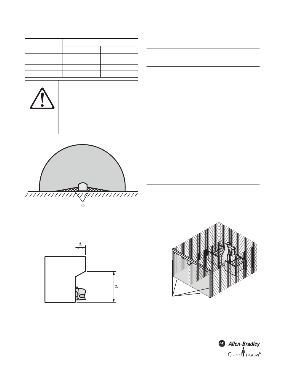
Mounting with hard guards
Figure 26: Example of mounting with hard guards
² Fit the hard guard such that the areas not covered by the safety laser
scanner are completely protected against personnel standing in them.
Mounting in a recess
Figure 27: Form of the recess
²
Design the recess
to be sufficiently deep enough that it
completely covers the area not protected by the safety laser
scanner (Figure 26) and such that standing in an unscanned area
is not possible.
4.2 Stationary Vertical Operation for Access
Protection
Access protection can be used when the access to the machine can be
defined by physical means. For access protection the SafeZone safety
laser scanner detects the entry of an entire body.
4.2.1 Safety distance
For access protection, a safety distance (S) must be maintained between
protective safety field and hazardous area. This safety distance ensures
that the hazardous point can only be reached after the dangerous state of
the machine has been completely stopped.
Figure 28: Access protection
Size of Unprotected Areas
Mounting Method
X
Y
Direct mounting
109 mm
618 mm
With mounting kit 1
112 mm
635 mm
With mounting kit 1 and 2
127 mm
720 mm
With mounting kit 1, 2 and 3
142 mm
805 mm
ATTENTION
Prevent unprotected areas.
Mount the SafeZone safety laser
scanner such that there are no
unprotected areas. Take one of the
precautions given in the following:
²
Install hard guards to prevent
standing behind.
²
Install the SafeZone safety laser
scanner in a recess.
IMPORTANT
Prevent crawling beneath the recess by
limiting the height of the recess such
that nobody can crawl beneath.
IMPORTANT
To ensure adequate access protection,
a response time of ~ 90 ms and a
resolution of 150 mm or finer is
required.
To protect the SafeZone multizone
scanner against inadvertent
adjustment or manipulation, use the
contour of the surrounding area as a
reference (see Section 3.4.3 “Using the
contour of the protective safety field as
a reference” on page 12).
Contours on the floor and the
side walls as reference