Original instructions, 1 system connection – Rockwell Automation 442L SafeZone Singlezone & Multizone Safety Laser Scanner User Manual
Page 33
R
SafeZone™ Safety Laser Scanner User Manual
10000073050, July 2011 31
Original instructions
Figure 48: Mounting on a cross
Figure 49: Reverse mounting, parallel
Section 5 — Electrical Installation
The electrical connections for the SafeZone safety laser scanner are made at
the system connector. It contains connections for the inputs, outputs and
the supply voltage. You can either make connections directly to the
terminal strip on the system connector or use a pre-assembled system
connector from Rockwell (see Section 5.3 “Pre-assembled system plugs” on
page 33).
5.1 System connection
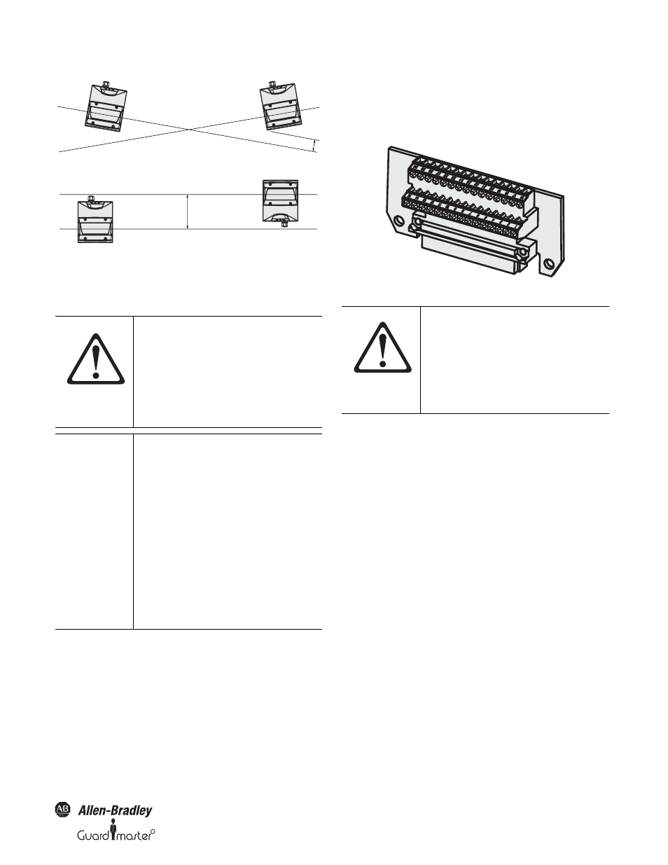
All input and output connections for the SafeZone safety laser scanner are
located on the system connector. This comprises of a
30-pin screw terminal connector and is located in the system connector.
Figure 50: Screw terminal strip on the system plug
ATTENTION
Switch the entire machine/system off
line.
The machine/system could
inadvertently start up while you are
connecting the devices.
Ensure that the entire machine/system
is disconnected during the electrical
installation.
IMPORTANT
Route all cables and connection cables
such that they are protected from
damage.
If you use the SafeZone safety laser
scanner for the protection of
hazardous areas: Ensure that any
control systems or other devices
forming part of the safety installation
meet the stipulated control category.
Ensure that the SafeZone safety laser
scanner is adequately protected
electrically. You will find the electrical
data necessary for determining the
correct fuse in Section 11.4 “Data sheet”
on page 45.
100 mm
200 mm
ATTENTION
If the cable fitting is missing or not
tightened, or if mounting screws are
missing or not tightened on the system
connector, the IP65 enclosure rating is
not met.
All inputs and outputs for the SafeZone
safety laser scanner are to be used only
in the context specified.