Original instructions, 3 re-commissioning – Rockwell Automation 442L SafeZone Singlezone & Multizone Safety Laser Scanner User Manual
Page 39
R
SafeZone™ Safety Laser Scanner User Manual
10000073050, July 2011 37
Original instructions
protective safety field shapes) and include these with the
documentation.
8.2.2 Regular inspection of the protective device by
qualified personnel
²
Check the system following the inspection intervals specified in
the national rules and regulations. This procedure ensures that
any changes on the machine or manipulations of the protective
device after the first commissioning are detected.
² If major changes have been made to the machine or the protective
device, or if the safety laser scanner has been modified or repaired,
check the equipment again as per the checklist in the annex (see Section
13.1 “Manufacturer’s checklist” on page 54).
8.2.3 Daily testing of the protective device by a
specialist or authorized personnel
The effectiveness of the protective device must be checked daily by a
specialist or by authorized personnel. The test must also be performed if
the operating mode is changed.
² The test must be carried out for the relevant preset monitoring case.
² Check the mechanical installation to ensure that all mounting screws
are secure and that the SafeZone safety laser scanner is properly aligned.
² Check each SafeZone safety laser scanner device for visible changes such
as damage, manipulation etc.
² Switch on the machine/equipment.
² Watch the LEDs on each SafeZone safety laser scanner.
² If at least one LED is not permanently lit when the machine/equipment
is switched on, it is to be assumed that there is a fault in the machine or
equipment. In this case the machine must be shut down immediately
and checked by a specialist.
² Deliberately obstruct the protective safety field without risk to any
personnel while the machine is running in order to test the effectiveness
of the entire system.
The LEDs of the SafeZone safety laser scanner device must change from
green to red and the hazardous movement must stop immediately.
Repeat this test at different points in the danger area and on all SafeZone
multizone safety laser scanner devices. If you discover any non-
conformance of this function, the machine/equipment must be shut
down immediately and checked by a specialist.
² For stationary applications, check that the danger area marked out on
the floor matches the shape of the protective safety field stored in the
SafeZone safety laser scanner and that any gaps are protected by
additional protective measures. In the case of mobile applications, check
that the moving vehicle actually stops at the field limits which are set in
the SafeZone safety laser scanner and listed on the information label in
the vehicle or in the configuration protocol. If you discover any non-
conformance of this function, the machine/equipment/vehicle must be
stopped immediately and checked by a specialist.
8.3 Re-commissioning
If the SafeZone safety laser scanner has previously been commissioned, but
the device replaced, the SafeZone safety laser scanner automatically reads
the saved configuration from the system connector. In this way acceptance
by a specialist is not necessary. However, the test in accordance with the
regulations for the daily test must be performed (see Section 8.2.3 “Daily
testing of the protective device by a specialist or authorized personnel” on
page 37).
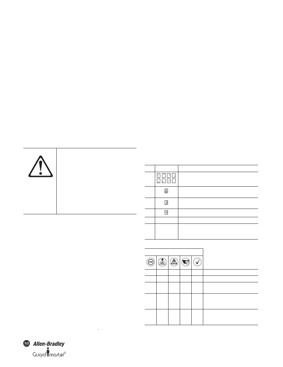
When you place a configured SafeZone safety laser scanner (e.g. after
replacement of the sensor head) back into operation, the following
indications are possible:
ATTENTION
No further operation if errors occur
during the test.
If any one of the following points is not
met, it is not permitted to continue to
work on the machine or operate the
vehicle. In this case the installation of
the SafeZone multizone safety laser
scanner must be checked by
specialized personnel (see Section
8.2.2 “Regular inspection of the
protective device by qualified
personnel” on page 37).
Step
Display
Meaning
1
Power-up cycle, testing the 7-segment display. All segments are
activated sequentially.
2
Power up cycle, during initial commissioning: Devices in
configuration mode
3
Waiting for partner device on the Bus connection (future
functionality)
4
Waiting for valid inputs
5
No display
The device is operational.
Other display
Safety lock activated. Malfunction in external conditions or in the
device itself. See Section 10.4 “Errors displayed by the 7-segment
display” on page 41.
Display
Meaning
l
m
m
m
m
Power-up cycle, step 1
l
l
l
l
m
Power-up cycle, step 2
l
m
l
m
m
The device is operational, object in protective
safety field and warning field.
m
m
l
m
l
Or:
The device is operational, object in warning
field.
m
m
m
m
l
Or:
The device is operational, no object in
protective safety field and warning field.
.
,
,
,
,
,
,
,
.