Installation and wiring, Cb1 physical connections, Cm1 physical connections – Rockwell Automation 193-DNCT DeviceNet Configuration Terminal User Manual User Manual
Page 11: Figure 1 - cat. no. 193-cm1 pinout, Chapter 2, Chapter
Rockwell Automation Publication 193-UM009B-EN-P - February 2013
7
Chapter
2
Installation and Wiring
Installation and Wiring
The DNCT ships complete with a 1 m cable (193-CB1) for connection to a
DeviceNet™ network. This cable has a plug connection to the terminal on one
end, and color coded bare leads on the other end. Alternately, a 1 m cable (193-
CM1) can be ordered that has a plug connection to the terminal on one end, and
a DeviceNet™ male micro style connector on the other end. A bezel mounting kit
(193-DNCT-BZ1) is available for mounting the terminal to a panel door.
193-CB1 Physical Connections
The 193-CB1 cable that ships with the Configuration Terminal has a plug
connection to the terminal on one end, and color coded bare leads on the other
end. The cable’s bare leads are wired to a DeviceNet™ connector according to the
following table:
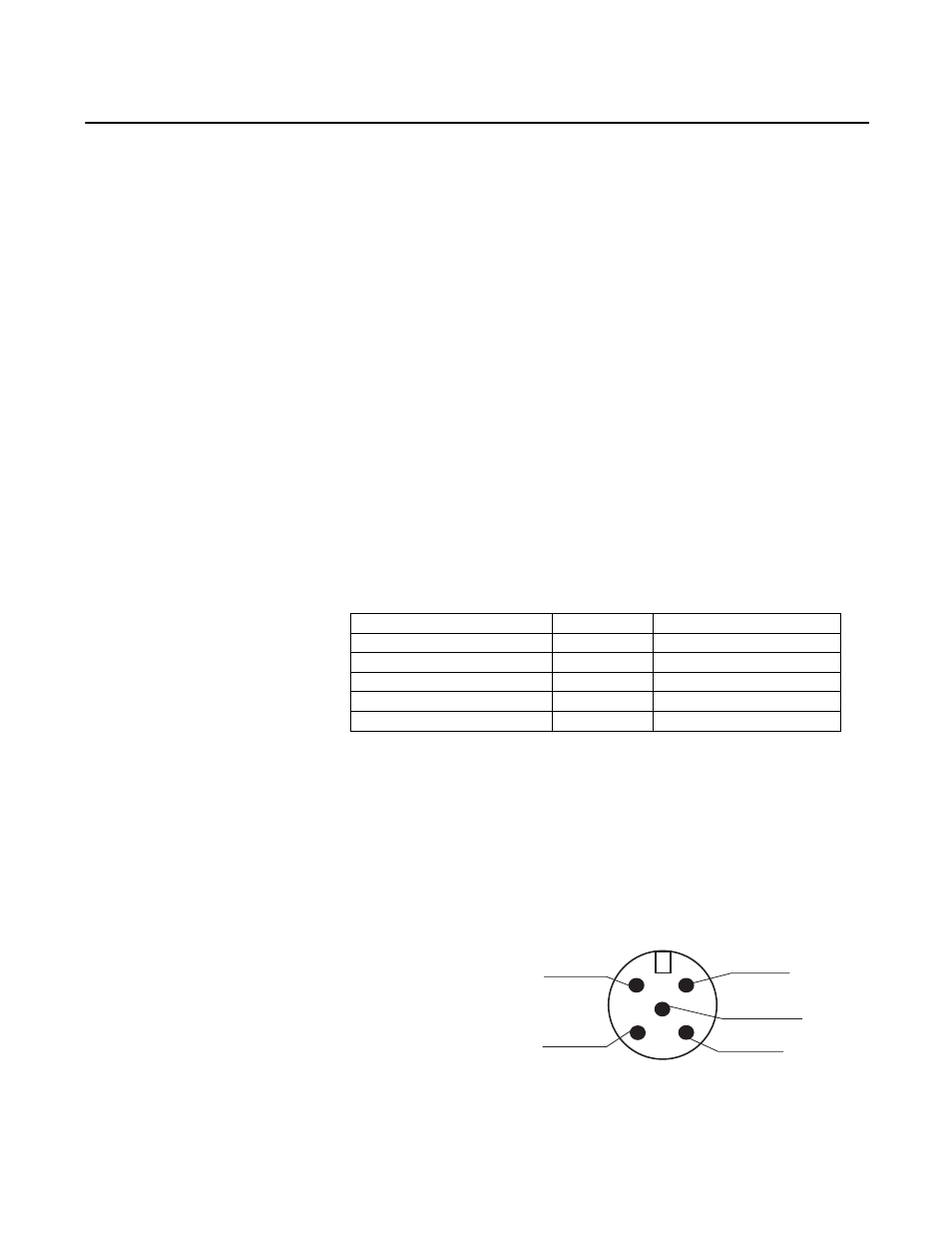
193-CM1 Physical Connections
The optional Cat. No.193-CM1 has a plug connection to the terminal on one
end and a DeviceNet™ male micro-style connector on the other end. The cable’s
micro connector pin-out is shown in Figure 1 -
Figure 1 - Cat. No. 193-CM1 Pinout
Signal
Function
Color
V-
Common
Black
Can_L
Signal Low
Blue
Drain
Shield
Non-insulated
Can_H
Signal High
White
V+
Power Supply
Red
Drain
Can_L
Can_H
V+
V-