Configuring and verifying key drive parameters – Rockwell Automation 20G PowerFlex 755 Drive Embedded EtherNet/IP Adapter User Manual
Page 22
22
Rockwell Automation Publication 750COM-UM001E-EN-P - October 2013
Chapter 2
Installing the Adapter
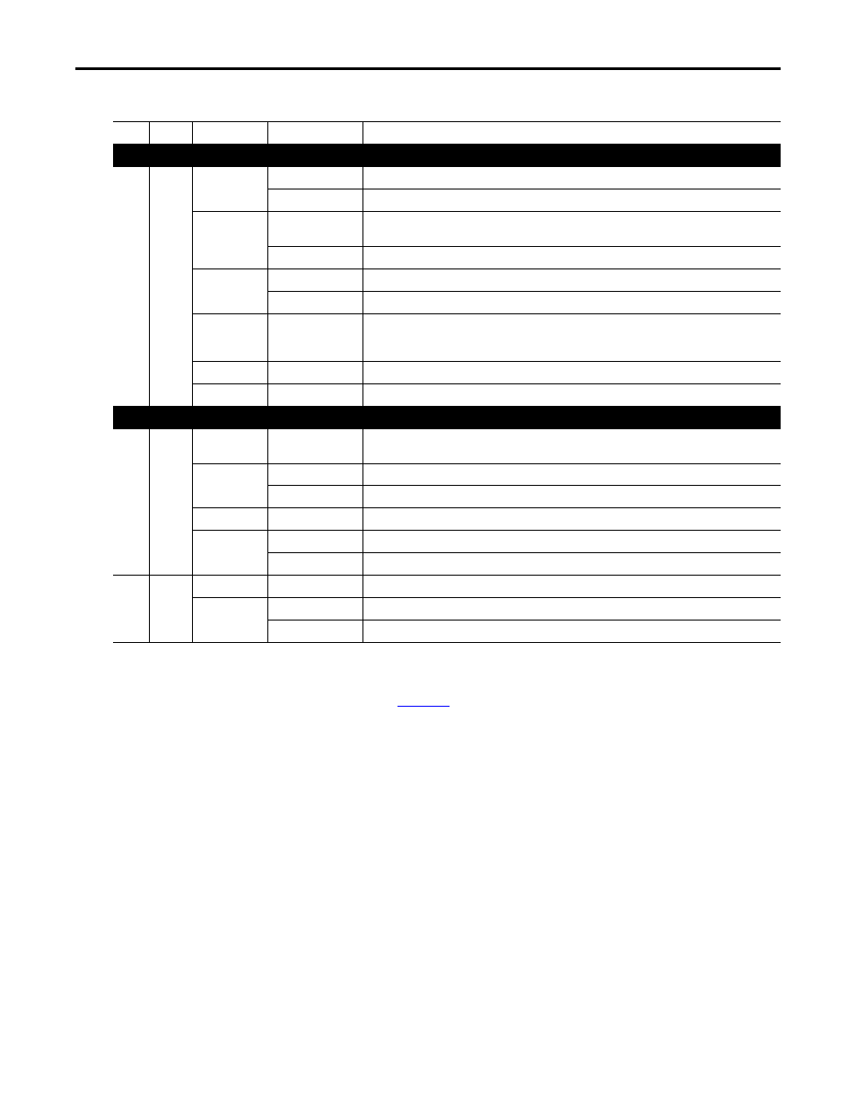
Table 1 - Drive and Adapter Start-Up Status Indications
After verifying correct operation, swing down the drive HIM bezel to its closed
position and install the drive cover. For more details on status indicator
operation, see
Configuring and Verifying Key Drive Parameters
The PowerFlex 755 drive can be separately configured for the control and
Reference functions in various combinations. For example, you could set the
drive to have its control come from a peripheral or terminal block with the
Reference coming from the network. Or you could set the drive to have its
control come from the network with the Reference coming from another
peripheral or terminal block. Or you could set the drive to have both its control
and Reference come from the network.
The following steps in this section assume that the drive will receive the Logic
Command and Reference from the network.
1.
Verify that drive Parameter 301 - [Access Level] is set to ‘1’ (Advanced) or
‘2’ (Expert) to access the required parameters in this procedure.
Item
Name
Color
State
Description
Drive STS Indicator
➊
STS
(Status)
Green
Flashing
Drive ready but not running, and no faults are present.
Steady
Drive running, no faults are present.
Yellow
Flashing
When running, a type 2 (non-configurable) alarm condition exists – drive continues to run. When stopped,
a start inhibit condition exists and the drive cannot be started (see drive parameter 933 - [Start Inhibit]).
Steady
A type 1 (user configurable) alarm condition exists, but the drive continues to run.
Red
Flashing
A major fault has occurred. Drive will stop. Drive cannot be started until fault condition is cleared.
Steady
A non-resettable fault has occurred.
Red/Yellow
Flashing Alternately
A minor fault has occurred. Use drive parameter 950 - [Minor Flt Config] to enable. If not enabled, acts like
a major fault. When running, the drive continues to run. System is brought to a stop under system control.
The fault must be cleared to continue.
Yellow/Green
Flashing Alternately
When running, a type 1 alarm exists.
Green/Red
Flashing Alternately
Drive is firmware updating.
Embedded EtherNet/IP Adapter Status Indicators
➋
ENET
Unlit
Off
Adapter and/or network is not powered, adapter is not properly connected to the network, or adapter
needs an IP address.
Red
Flashing
An EtherNet/IP connection has timed out.
Steady
Adapter failed the duplicate IP address detection test.
Red/Green
Flashing Alternately
Adapter is performing a self-test.
Green
Flashing
Adapter is properly connected, but is not communicating with any devices on the network.
Steady
Adapter is properly connected and communicating on the network.
➌
LINK
Unlit
Off
Adapter is not powered or is not transmitting on the network.
Green
Flashing
Adapter is properly connected and transmitting data packets on the network.
Steady
Adapter is properly connected, but is not transmitting on the network.