Rockwell Automation 20B PowerFlex 700 Drive - Frame 7 Components Replacement User Manual
Page 44
44
Rockwell Automation Publication 20B-IN017B-EN-P - September 2011
Chapter 3 Component Replacement Procedures
e. Remove the conductive tape from the IGBT module and
immediately install a new Gate Interface Board.
for the second IGBT module.
3. Reconnect the Gate Interface Board connections.
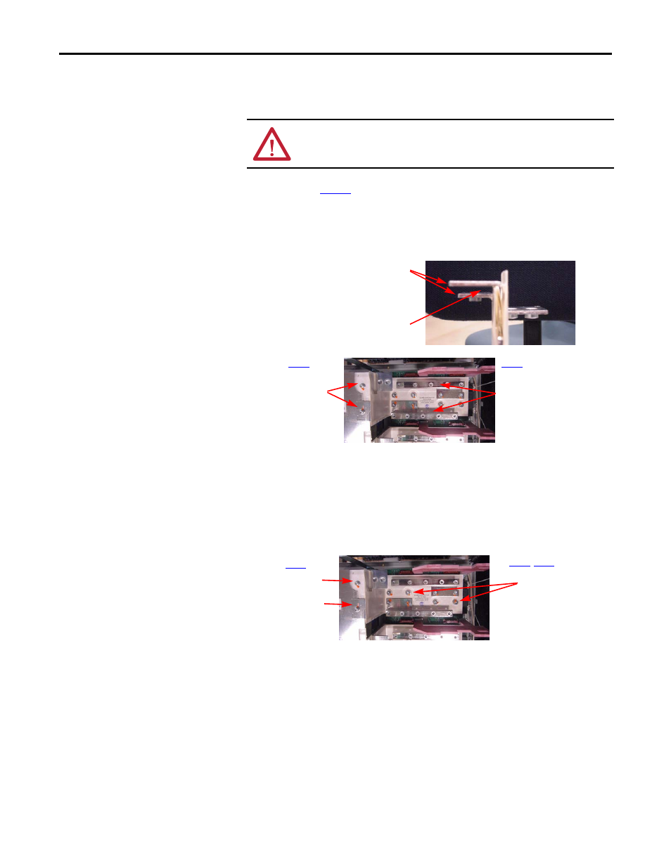
4. Place the IGBT Bus Bar on the IGBT modules (over the Gate Interface
Boards) with its flanges fitting over and under the Transitional Bus Bar.
5. Install M6 screws for the IGBT module Bus Bar but do not torque at
this time.
6. Install the Inverter Snubber Brackets parallel to each other but do not
torque at this time.
7. Install remaining M6 screws for the IGBT module and Bus Bar.
8. Torque all screws on the Inverter Snubber Brackets and on the IGBT
module Bus Bar to 9.0 N•m (80 lb•in)
9. Torque DC+ and DC– M6 screws to 5.9 N•m (52 lb•in)
10. Install the new Snubber Board with the terminal lug towards the outside
of the drive. Torque screws to 5.6 N•m (50 lb•in)
11. Position each Motor Bus Bar but do not torque mounting screws yet.
12. Position each Current Transducer and install screws but do not torque
yet.
After the conductive tape is removed, the IGBT module’s gate terminals
must not be exposed longer than one minute.
IGBT Bus Bar
Flanges
Transitional Bus Bar fits here
Inverter Snubber Brackets
Be sure to orient brackets as
shown.
IGBT Bus Bar
screws
Remaining IGBT Bus
Bar screws
DC+
DC–