Remove stacking panel – Rockwell Automation 20B PowerFlex 700 Drive - Frame 7 Components Replacement User Manual
Page 22
22
Rockwell Automation Publication 20B-IN017B-EN-P - September 2011
Chapter 2 Basic Component Removal Procedures
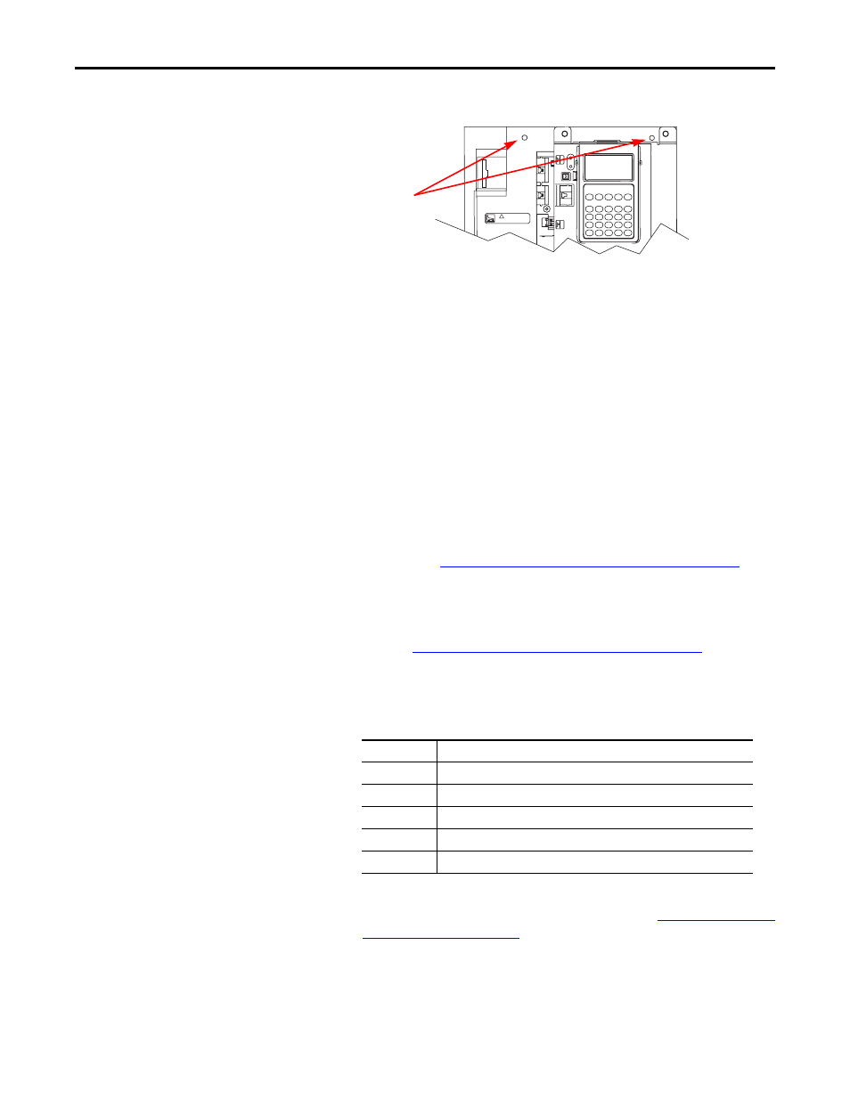
6. Remove the two nuts at the top of the Main Control Panel.
7. Remove Main Control Panel; support.
8. Disconnect wire harnesses from TB11 to the Switch Mode Power
Supply Board ( J4 connector) and at TB1 and TB2 on the Power
Interface Board.
9. Label and disconnect all customer wiring from TB11.
10. Carefully set the Main Control Panel aside.
Install Components
When instructed for the component you are replacing, reinstall the Main
Control Panel Assembly components in the reverse order of removal.
Remove Stacking Panel
Refer to the figures in
Component Diagrams and Torque Specs on page 13
these instructions.
Remove Components
Remove Main Control Panel Assembly on page 21
2. Remove remaining wiring harnesses from the Power Interface Board. Do
not disconnect the wiring between the Power Interface Board and the
Switch Mode Power Supply Board.
3. Disconnect the Main Control Panel Assembly Thermal Sensor wire
from the Monitor Wire. (See diagram at the start of
.)
4. Remove the two screws at the bottom of the Stacking Panel for the
Power Interface and the Switch Mode Power Supply Boards. Remove the
panel by sliding it up and out.
CAUTION
HOT SURFACES
!
Connector
Connected Components
J14, J15, J16
U, V, W Phase CT
J24
+Bus IN of Power Interface Board to J1 of Precharge Board
J7
Main Control Panel Thermal Sensor
J18
U, V, W negative gates
J23
U, V, W positive gates