Rockwell Automation 20B PowerFlex 700 Drive - Frame 7 Components Replacement User Manual
Page 43
Rockwell Automation Publication 20B-IN017B-EN-P - September 2011
43
Component Replacement Procedures Chapter 3
10. Remove the Gate Interface Boards (three (3) screws) and discard.
11. Remove the six (6) screws for the IGBT modules.
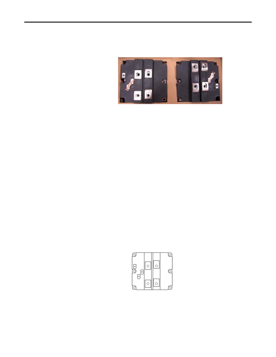
12. Remove the IGBT modules by tipping the top edge out first. Discard.
Install Components
1. Perform the following steps for one IGBT module at a time.
a. Using isopropyl alcohol, thoroughly clean the surface of the
Heatsink.
Important: The replacement IGBT modules are supplied with a
conductive tape across the terminals. Do Not remove the
tape until instructed.
b. Verify that the mounting surface of the new IGBT module is clean.
If not, clean with isopropyl alcohol.
c. Using a 3" putty knife or similar tool, apply a thin even coating of
the supplied thermal grease to the mounting surface of the IGBT
module.
Use enough thermal grease to create a conductive coating, but not
so much that the two surfaces can rock.
Important: In the next step, take care to not disturb any of the thermal grease on
the IGBT module.
d. Place the IGBT module on the Heatsink and install with supplied
screws and tighten using this torque sequence:
Note: Picture shows
new IGBT modules
with conductive
tape, but existing
modules will not
have conductive
tape.
IGBT Torque Sequence
First Sequence: 0.7 N-m (6.0 lb.-in.)
Final Sequence: 3.6 N-m (32 lb.-in.)
➎
➊
➌
➍
➋
➏