Inverter snubber board – Rockwell Automation 20B PowerFlex 700 Drive - Frame 7 Components Replacement User Manual
Page 38
38
Rockwell Automation Publication 20B-IN017B-EN-P - September 2011
Chapter 3 Component Replacement Procedures
7. Loosen the mounting bracket screws and align the CT assembly on the
bus bar with the remaining transducers.
8. Torque the mounting bracket screws to 5.9 N•m (52 lb•in)
9. Reconnect the wiring harness. Secure with a wire tie.
10. Replace all safety shields and enclosure covers before applying power to
the drive.
Inverter Snubber Board
Important: The Inverter Snubber Board and its associated Resistor do not need
to be replaced at the same time.
Refer to the figures in
Component Diagrams and Torque Specs on page 13
these instructions.
Remove Components
1. Read and follow the
and
.
Remove Main Control Panel Assembly on page 21
Remove Stacking Panel on page 22
Remove Precharge Board Assembly on page 23
5. Locate the Inverter Snubber Board to be replaced.
6. Remove the Current Transducer assembly mounted over the board to be
replaced.
a. Disconnect the wiring harness from the transducer board. Clip the
wire tie and remove the wiring harness.
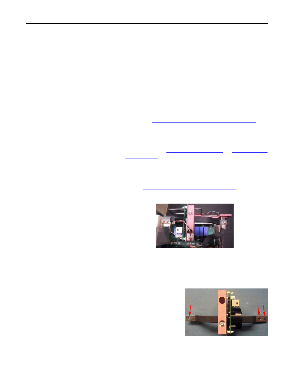
b. Remove the three
button head screws
that secure the bus bar.
Move the bus bar and
transducer to an ESD-
safe flat surface.