1 - component diagrams and torque specs, Drive components, Chapter 1 – Rockwell Automation 20B PowerFlex 700 Drive - Frame 7 Components Replacement User Manual
Page 13: Component diagrams and torque specs, Es in, Component, Chapter, Ac input drive is shown
Rockwell Automation Publication 20B-IN017B-EN-P - September 2011
13
Chapter
1
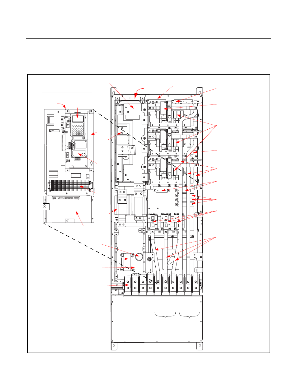
Component Diagrams and Torque Specs
Drive Components
AC input drive is shown.
+DC
USE 75
°
COPPER WIRE ONLY
TORQUE LARGE TERMINALS TO 10 N-m (87LB-IN)
-DC
PE
PE
R-L1
T-L3
U-M1
V-M2
W-M3
S-L2
RISK OF SHOCK
REPLACE AFTER
SERVICING
!
DANGER
TB11
25 AMPERES RMS
MAXIMUM
CAUTION
HOT SURFACES
ALLEN-BRADLEY
MADE IN U.S.A.
PE
!
Converter Snubber Boards (3)
with Converter Power SCR
Modules underneath
MOV Location
Inverter Snubber Boards (U,
V, W)
Inverter Snubber Resistors
Current Transducer
Gate Interface Board (U)
(V and W not shown)
Heatsink Thermal
Sensor location
Main Control Panel Assembly
Motor Bus Bars
AC Bus Bars (R, S, T)
W
Inverter Power Module IGBTs
(U, V, W) (under Inverter
Snubber Board)
U
V
W Phase
U Pha
se
V Phase
T Phase
R Phase
S Phase
Precharge Board
Assembly
TB2
J3
J1
J2
Po
w
er
In
te
rf
ac
e
Bo
ar
d
(u
nder Ma
in
C
on
tr
ol
P
anel)
TB11
Transitional Bus Bar
HIM
Co
mmunications
Mo
du
le
Mai
n C
on
tr
ol P
ane
l
(Sta
ck
in
g P
anel
(und
ernea
th)
Bu
s F
use
Balancing Resistors
DC Lin
k
Ch
ok
e
Main Control
Panel Thermal
Sensor
DC Capacitor Bank
(under Transitional Bus Bar)
Switc
h Mo
de P
ow
er S
up
ply B
oar
d
(u
nd
er
Mai
n C
on
tr
ol P
ane
l)
Power Terminal Block
Transformer
Capacitor
for Fan
Motor
Connections
AC Power Input
Connections