Inverter snubber resistor – Rockwell Automation 20B PowerFlex 700 Drive - Frame 7 Components Replacement User Manual
Page 40
40
Rockwell Automation Publication 20B-IN017B-EN-P - September 2011
Chapter 3 Component Replacement Procedures
Inverter Snubber Resistor
Important: The Inverter Snubber Board and its associated Resistor do not need
to be replaced at the same time. Test the Resistor as instructed below
before replacing it.
Refer to the figures in
Component Diagrams and Torque Specs on page 13
these instructions.
Remove Components
1. Read and follow the
and
.
2. Remove safety shields as needed.
3. Test all Snubber Resistors.
a. Using pliers, remove the push-on J1 connector from the Inverter
Snubber Board. Place one probe of a volt ohm meter inside the
connector.
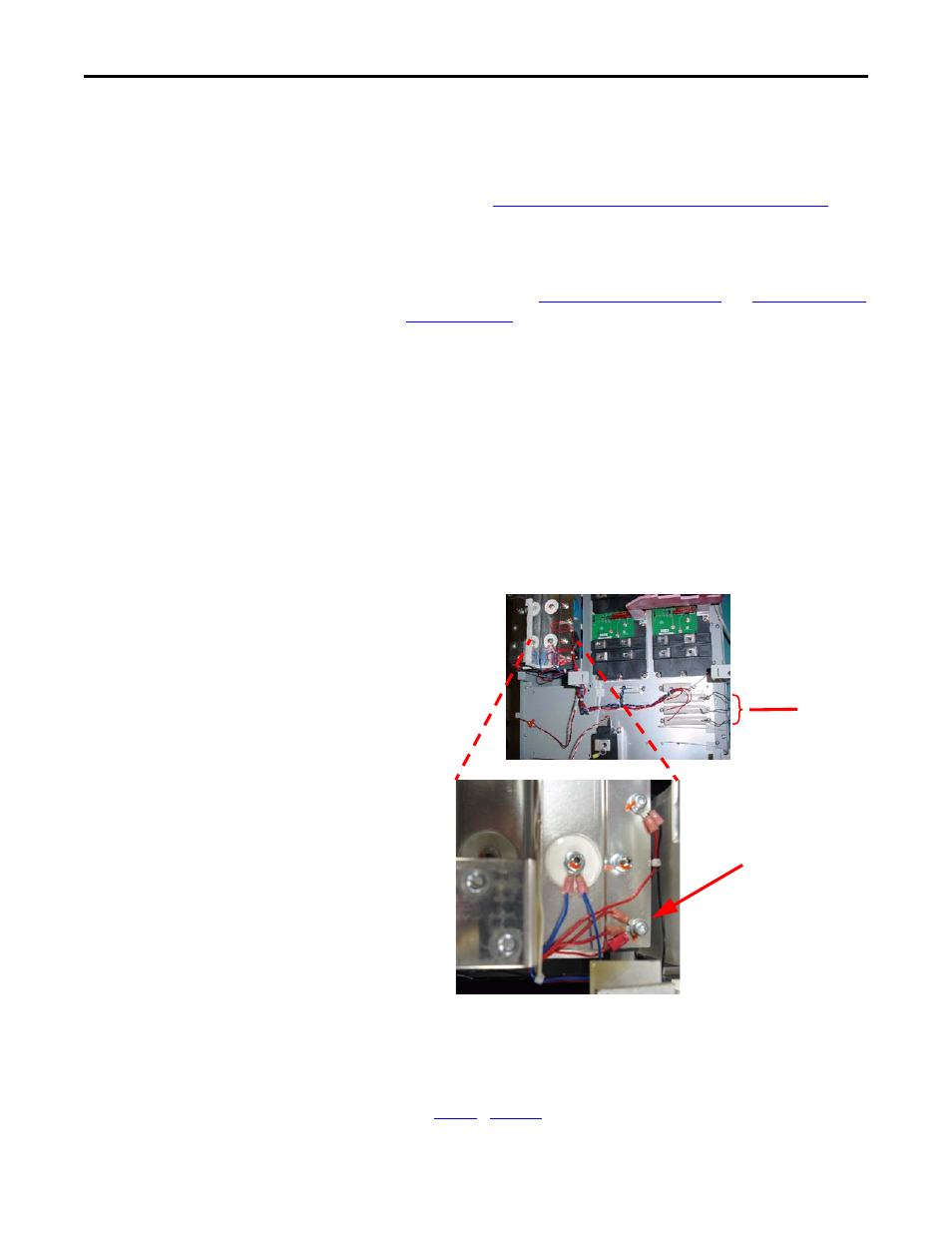
b. At the bottom right of the DC capacitor bank, under the
Transitional Bus Bar, locate the screw with several connections
(typically three, with one for each Snubber Resistor). Place the other
probe of the volt ohm meter on that screw. The reading should be 8
ohms.
c. If the reading is 8 ohms, the Inverter Snubber Resistor does not need
to be replaced and this test and this procedure are complete; do not
perform the remainder of this procedure.
d. If the reading is other than 8 ohms, continue with the instructions in
…
to replace any faulty Resistor.
Inverter
Snubber
Resistors
Test Screw
(common point)
Shown with
Transitional Bus Bar
and other
components
removed