Hardware enable circuitry (vector control only) – Rockwell Automation 20B PowerFlex 700 Installation Instructions - Frames 0…6 User Manual
Page 57
Rockwell Automation Publication 20B-IN019E-EN-P - July 2013
57
PowerFlex 700 Adjustable Frequency AC Drive – Frames 0…6
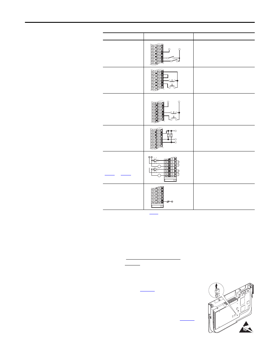
Hardware Enable Circuitry (Vector Control Only)
By default, the user can program a digital input as an Enable input. The status of
this input is interpreted by drive software. If the application requires the drive to
be disabled without software interpretation, a “dedicated” hardware enable
configuration can be utilized. This is done by removing a jumper and wiring the
enable input to “Digital In 6.”
1.
Remove the I/O Control Cassette & cover as
described on
page 53
.
2.
Locate & remove Jumper J10 on the Main
Control Board (see diagram).
3.
Re-assemble cassette.
4.
Wire Enable to “Digital In 6” (see
page 54
).
5.
Verify that [Digital In6 Sel], parameter 366 is
set to “1, Enable.”
2-Wire Control
Reversing
(1)
External supply
(I/O Board dependent)
• Set Digital Input:#1:
Parameter 361 = “8, Run Forward”
• Set Digital Input #2:
Parameter 362 = “9, Run Reverse”
3-Wire Control
Internal supply
• No Changes Required
3-Wire Control
External supply (I/O Board
dependent). Requires 3-wire
functions only ([Digital In1
Sel]). Using 2-wire selections
causes a type 2 alarm.
• No Changes Required
Digital Input
PLC Output Card (Board
dependent).
• No Changes Required
Digital Output
Relays (two at terminals
14…16) shown in powered
state with drive faulted. See
page 54
and
page 55
.
• Select Source to Activate:
Parameters 380/384
Enable Input
• Configure with parameter 366
For dedicated hardware Enable:
Remove Jumper J10 (see below)
(1) Refer to the Attention statement on
page 52
for important bipolar wiring information.
(2) Important: Programming inputs for 2 wire control deactivates all HIM Start buttons unless parameter 192, [Save HIM Ref], bit 1
[Manual Mode] = “1.” This allows the HIM to control Start and Jog.
Input/Output
Connection Example
Required Parameter Changes
25
27
28
Run Rev.
Run Fwd.
115V/
+24V
Neutral/
Common
Start
24
25
26
27
28
Stop
Start
25
27
28
Stop
115V/
+24V
Neutral/
Common
25
27
28
Control from
Prog. Controller
Neutral/
Common
10k Ohm, 2 Watt
Power Source
11
12
13
14
15
16
Fault
NOT Fault
NOT Run
Run
or
32
E
N
A
B
LE
JU
M
P
E
R
J10