Power and ground wiring, Safety ground - pe – Rockwell Automation 20B PowerFlex 700 Installation Instructions - Frames 0…6 User Manual
Page 31
Rockwell Automation Publication 20B-IN019E-EN-P - July 2013
31
PowerFlex 700 Adjustable Frequency AC Drive – Frames 0…6
Power and Ground Wiring
The drive Safety Ground - PE must be connected to system ground.
Ground
impedance must conform to the requirements of national and local industrial
safety regulations and/or electrical codes. Periodically check the integrity of all
ground connections.
For installations within a cabinet, a single safety ground point or ground bus bar
connected directly to building steel must be used. All circuits including the AC
input ground conductor must be grounded independently and directly to this
point/bar.
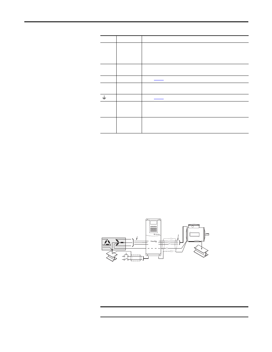
Typical Grounding
Safety Ground - PE
This is the safety ground for the drive that is required by code. This point must be
connected to adjacent building steel (girder, joist), a floor ground rod or bus bar
(see above). Grounding points must comply with national and local industrial
safety regulations and/or electrical codes.
Terminal
Description
Notes
BR1
BR2
DC Brake (+)
DC Brake (–)
DB Resistor Connection - Important: Only one DB resistor can be used with Frames
0…3. Connecting an internal & external resistor could cause damage.
Twisted pair wiring must be used from these terminals to the resistor. Wiring must be
routed separately from other cabling.
DC+
DC–
DC Bus (+)
DC Bus (–)
DC Input/Brake Connections (chopper and resistor).
PE
PE Ground
Refer to
page 29
for location on Frame 3 drives
PS+
PS–
AUX (+)
AUX (–)
Auxiliary Control Voltage
Motor Ground
Refer to
page 29
for location on Frame 3 drives
U
V
W
U (T1)
V (T2)
W (T3)
To Motor/Load
R
S
T
R (L1)
S (L2)
T (L3)
AC Line Input Power
Three-Phase = R, S & T
Single-Phase = R & S Only (refer to User Manual for details)
IMPORTANT
Do Not discard or replace grounding hardware.
U (T1)
V (T2)
W (T3)
R (L1)
S (L2)
T (L3)
PE
SHLD