Minimum mounting clearances – Rockwell Automation 20B PowerFlex 700 Installation Instructions - Frames 0…6 User Manual
Page 10
10
Rockwell Automation Publication 20B-IN019E-EN-P - July 2013
PowerFlex 700 Adjustable Frequency AC Drive – Frames 0…6
Table 2 - Acceptable Surrounding Air Temperature & Required Actions
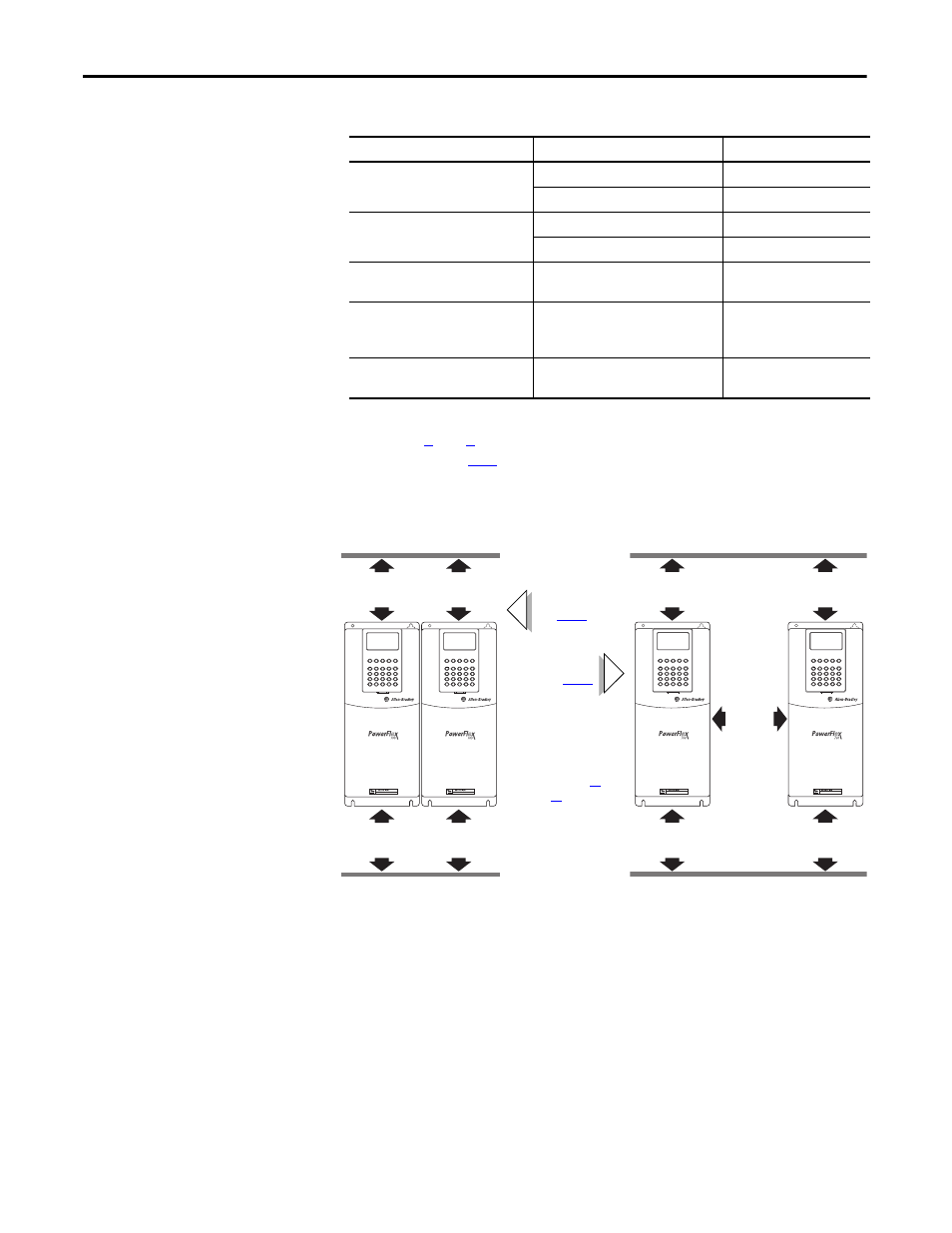
Minimum Mounting Clearances
Specified vertical clearance requirements (indicated above) are intended to be
from the drive to the closest object that can restrict airflow through the drive heat
sink and chassis. The drive must be mounted in a vertical orientation as shown
and must make full contact with the mounting surface. Do not use standoffs or
spacers. In addition, inlet air temperature must not exceed the product
specification.
Enclosure Rating
Temperature Range
Drive
IP20, NEMA/UL Type 1
(with Top Label)
(1)
(1) Removing the adhesive top label from the drive changes the NEMA/UL enclosure rating from Type 1 to Open. Frames 5 and 6 do not
have a top label.
0…40 °C (0…104 °F)
Frames 0…4, All Ratings
0…50 °C (0…122 °F)
Frames 5…6, Most Ratings
(2)
(2) Refer to
pages
34
through
41
for exceptions.
IP20, NEMA/UL Type Open
(Top Label Removed)
(1)
0…50 °C (0…122 °F)
Frames 0…6, Most Ratings
(2)
0…45 °C (0…113 °F)
20BC072 Only
IP00, NEMA/UL Type Open
(Top Label & Vent Plate Removed)
0…50 °C (0…122 °F)
20BC072 Only
(3)
(3) To remove vent plate (see
page 11
for location), lift top edge of plate from the chassis. Rotate the plate out from the back plate.
Flange Mount
Front: IP00, NEMA/UL Type Open
Back/Heat Sink: IP54, NEMA/UL Type 12
0…55 °C (0…131 °F) Front (Inside Encl.)
0…40 °C (0…104 °F) Back (External)
Frames 5…6
Stand-alone/Wall Mount
IP54, NEMA/UL Type 12
0…40 °C (0…104 °F)
Frames 5…6
101.6 mm
(4.0 in.)
101.6 mm
(4.0 in.)
101.6 mm
(4.0 in.)
101.6 mm
(4.0 in.)
PWR
STS
PORT
MOD
NET A
NET B
PWR
STS
PORT
MOD
NET A
NET B
101.6 mm
(4.0 in.)
101.6 mm
(4.0 in.)
50.8 mm
(2.0 in.)
101.6 mm
(4.0 in.)
101.6 mm
(4.0 in.)
PWR
STS
PORT
MOD
NET A
NET B
PWR
STS
PORT
MOD
NET A
NET B
Airflow through the drive
must not be impeded.
Refer to pages
11
through
20
for detailed
dimension information.
No Adhesive Label
(see
Table 2
)
With Adhesive Label
(see
Table 2
)