Rockwell Automation 20B PowerFlex 700 Installation Instructions - Frames 0…6 User Manual
Page 38
38
Rockwell Automation Publication 20B-IN019E-EN-P - July 2013
PowerFlex 700 Adjustable Frequency AC Drive – Frames 0…6
Notes
(1)
Minimum protection device size is the lowest rated device that supplies maximum protection without nuisance tripping.
(2)
Maximum protection device size is the highest rated device that supplies drive protection. For US NEC, minimum size is 125% of
motor FLA. Ratings shown are maximum.
(3)
Circuit Breaker - inverse time breaker. For US NEC, minimum size is 125% of motor FLA. Ratings shown are maximum.
(4)
Motor Circuit Protector - instantaneous trip circuit breaker. For US NEC minimum size is 125% of motor FLA. Ratings shown are
maximum.
(5)
Bulletin 140M with adjustable current range must have the current trip set to the minimum range that the device will not trip.
(6)
Manual Self-Protected (Type E) Combination Motor Controller, UL listed for 208 Wye or Delta, 240 Wye or Delta, 480Y/277 or 600Y/
347. Not UL listed for use on 480V or 600V Delta/Delta, corner ground, or high-resistance ground systems.
(7)
The AIC ratings of the Bulletin 140M Motor Protector Circuit Breakers can vary. See
Bulletin 140M Motor Protection Circuit Breakers
Application Ratings
.
(8)
Maximum allowable rating by US NEC. Exact size must be chosen for each installation.
(9)
UL Type 12/IP54 (flange mount) heat sink ambient temperature rating is 40° C/ambient of unprotected drive portion (inside
enclosure) is 55° C. The ambient temperature for the UL Type 12/IP54 stand-alone drives is 40° C.
(10)
Must remove top label and vent plate, drive enclosure rating is IP00, NEMA/UL Type Open.
(11)
Drive frames 0…4 temperature rating is for NEMA/UL Type Open. The adhesive top label must be removed to operate drive at this
temperature. Frames 5 & 6 do not have a top label.
(12)
Drives have dual current ratings; one for normal duty applications, and one for heavy duty applications. The drive can be operated at
either rating.
(13)
Note: 600V class drives below 77 Amps (Frames 0…4) are declared to meet the Low Voltage Directive. It is the responsibility of the
user to determine compliance to the EMC directive.
(14)
When using a Manual Self-Protected (Type E) Combination Motor Controller, the drive must be installed in a ventilated or non-
ventilated enclosure with the minimum volume specified in this column. Application specific thermal considerations can require a
larger enclosure.
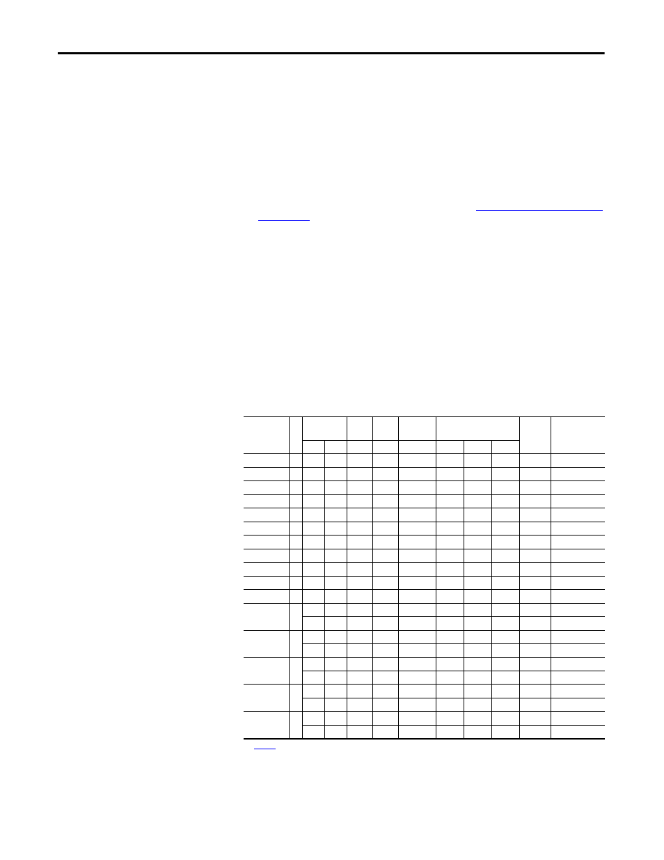
325 Volt DC Input Protection Devices
Drive Catalog
Number
Fr
am
e Hp Rating
PWM
Freq.
Temp.
(1)
DC Input
Ratings
Output Amps
Fuse
Non-Time Delay
Fuse
(2) (11)
ND
HD
kHz
°C
Amps
Cont.
1 Min.
3 Sec.
20BB2P2
0
0.5
0.33
4
50
2
2.2
2.4
3.3
5
JKS-5
20BB4P2
0
1
0.75
4
50
3.8
4.2
4.8
6.4
10
JKS-10
20BB6P8
1
2
1.5
4
50
6.9
6.8
9
12
15
HSJ15
20BB9P6
1
3
2
4
50
9.7
9.6
10.6
14.4
20
HSJ20
20BB015
1
5
3
4
50
16
15.3
16.8
23
30
HSJ30
20BB022
1
7.5
5
4
50
23.3
22
24.2
33
45
HSJ45
20BB028
2
10
7.5
4
50
30
28
33
44
60
HSJ60
20BB042
3
15
10
4
50
45
42
46.2
63
90
HSJ90
20BB052
3
20
15
4
50
55
52
63
80
100
HSJ100
20BB070
4
25
20
4
50
75.3
70
78
105
150
HSJ150
20BB080
4
30
25
4
50
86.8
80
105
140
175
HSJ175
20BN104
(3)
5
40
–
4
50
114.1
104
115
175
200
HSJ200
–
30
4
50
85.8
80
120
160
200
HSJ200
20BN130
(3)
5
50
–
4
50
142.6
130
143
175
200
HSJ200
–
40
4
50
114.1
104
156
175
200
HSJ200
20BN154
(3)
6
60
–
4
50
169
154
169
231
300
HSJ300
–
50
4
50
142.6
130
195
260
300
HSJ300
20BN192
(3)
6
75
–
4
50
210.6
192
211
288
350
HSJ350
–
60
4
50
169
154
231
308
350
HSJ350
20BN260
(3)
6
100
–
2
45
285.3
260
286
390
400
HSJ400
–
75
2
50
210.6
205
305
410
400
HSJ400
See
page 41
for notes.