Rockwell Automation 20B PowerFlex 700 Installation Instructions - Frames 0…6 User Manual
Page 46
46
Rockwell Automation Publication 20B-IN019E-EN-P - July 2013
PowerFlex 700 Adjustable Frequency AC Drive – Frames 0…6
Fram
e
Vo
lt
ag
e
Code
Current
Ra
ti
ng
Factory Default Jumper Settings
Power Source Type
MOV/Input
Filter Caps
(1) (2)
DC Bus Common
Mode Caps
3…4
All Drives (continued)
B…E
All
PE_MOV
Installed
PE-CAP
Installed
Solid Ground
• Verify that jumpers are installed at the
“PE_CAP” and “PE_MOV” locations.
Non-Solid Ground
• Remove jumpers at the “PE_CAP” and
“PE_MOV” locations.
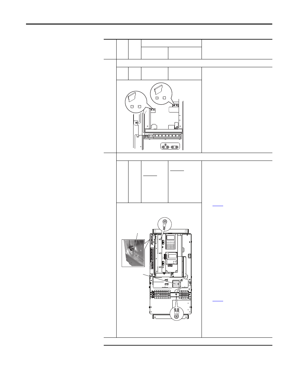
5
IP20, NEMA/UL Type 1 and Open Drives
B
C
D
H
J
N
P
R
All
except
C140
Two green/
yellow wires
connected to the
Power Terminal
Block rail
Green/yellow wire is
connected to ground
Solid Ground
1. CM Cap jumper wire must be connected to
ground with a metal screw. Verify, and if
necessary:
• Newer Drives - Remove the nylon screw/
spacer and insert a metal M5 x 8 screw.
Torque to 3.2 N•m (28 lb•in).
• Older Drives - Remove the I/O Cassette (see
page 53
). The green/yellow CM Cap jumper
wire is on the back of chassis and must be
connected to ground with a metal screw.
Remove the insulation from the wire
terminal and connect to chassis with a
metal M5 x 12 screw. Torque to 3.2 N•m (28
lb•in).
2. MOV/Input Filter Cap jumper wires must be
connected to ground with a metal screw.
Verify, and if necessary, remove the nylon
screw/spacer and insert a metal M5 x 12
screw.
Non-Solid Ground
1. CM Cap jumper wire must be insulated from
ground. Verify, and if necessary:
• Newer Drives - Remove the metal screw
and insert a M5 x 15 nylon screw/spacer.
• Older Drives - Remove the I/O Cassette (see
page 53
). Insulate/secure jumper wire to
guard against unintentional contact with
chassis or components.
2. MOV/Input Filter Cap jumper wires must be
insulated from ground with a nylon screw/
spacer. Verify, and if necessary, remove the
metal screw and insert a M5 x 20 nylon screw/
spacer.
Frame 5 continued on next page
(1) AC input drives only. MOV’s and input filter caps do not exist on DC input drives.
(2) When removing MOV’s, the input filter capacitor must also be removed.
BR1 BR2 DC+ DC- U/T1 V/T2 W/T3 R/L1 S/L2
T/L3
PE MOV
PE CAP
75C Cu Wire
3 AWG [25MM
2
] Max.
16 IN. LBS.
1.8 N-M
} TORQUE
WIRE
STRIP
CONTROL
PO
WER
AUX IN
+ –
SHLD
PE
75C Cu Wire
6 AWG [10MM2] Max.
BR1 BR2
12 IN. LBS.
1.4 N-M
} TORQUE
PE_CAP
PE_MOV
CM Cap
MOV
WIRE RANGE: 14-1/0 AWG (2.5-35 MM2)
TORQUE: 32 IN-LB (3.6 N-M)
STRIP LENGTH: 0.67 IN (17 MM)
USE 75 C CU WIRE ONLY
POWER TERMINAL RATINGS
WIRE RANGE: 6-1/0 AWG (16-35 MM2)
TORQUE: 44 IN-LB (5 N-M)
STRIP LENGTH: 0.83 IN (21 MM)
GROUND TERMINAL RATINGS (PE)
300 VDC EXT PWR SPLY TERM (PS+, PS-)
WIRE RANGE: 22-10 AWG (0.5-4 MM2)
TORQUE: 5.3 IN-LB (0.6 N-M)
STRIP LENGTH: 0.35 IN (9 MM)
17
21
INPUT AC
OUTPUT
Optional
Communications
Module
9
CM Cap -
Older Drives
MOV / Input Filter Cap
MOV
CM Cap - Newer Drives