8 standard wi-i/o 9-u2 i/o (basic i/o), 9 i/o configuration – Weidmuller WI-I/O-9-U2: Wireless Mesh I/O & Gateway User Manual V1.2.2 User Manual
Page 62
61
4.3.8 Standard WI-I/O 9-U2 I/O (Basic I/O)
The following table shows the basic onboard I/O available in a standard WI-I/O 9-U2
module with no expansion I/O connected. For a more detailed I/O map (showing the full
register range), see Appendix B:
“I/O Store Registers” at the end of the manual.
Address
Input / Output Description
0001 - 0008
Local DIO1
– DIO8 (as Outputs)
10001 - 10008 Local DIO1
– DIO8 (as Inputs)
10009 - 10020
Setpoint status from Analog inputs 1 through 12. (AI1, 2, 3, 4
Current Mode), (Internal Supplies), (AI1, 2, 3, 4 Voltage Mode)
30001 - 30004
Local AI1
– AI4 (Current Mode)
(AI1& AI2 - 4-20mA diff, AI3 & AI4 - 4-20mA Sink)
30005
30006
30007
30008
Local Supply voltage (0-40V default scaling)
Local 24V loop voltage (0-40V default scaling)
Local Battery voltage (0-40V default scaling)
WI-I/O-EX-1-S Expansion I/O Supply Voltage (0-40V default
scaling)
30009 - 30012 Local AI1
– AI4 (Voltage Mode) (AI1& AI2 - 0-20V, AI3 & AI4 - 0-5V)
30013 - 30016 Local Pulse input rates PI1
– PI4
36001 - 36008
Local Pulsed input counts
– (PI1 Most significant word is 36001 and
Least significant word is 36002)
38001 - 38032 Local Analog inputs as Floating point values (mA, Volts or Hz)
40001 - 40002 Local AO1
– AO2
48001 - 48002 Local AO1
– AO2 as floating point values (mA)
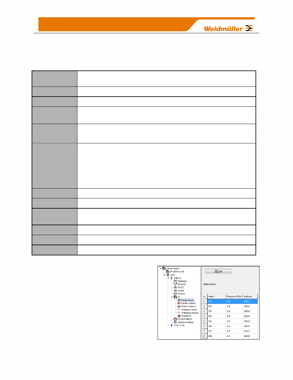
4.3.9 I/O Configuration
I/O configuration is done using the
Configuration software and each I/O has
different characteristics that can be tailored to
certain applications.
Selecting IO from within the Project Tree in
the Configuration utility will display
configuration options for the I/O, the
configuration display (explained below) will
provide an overview for all of the configurable
Figure 41 - I/O configuration