2 boot sequence “pwr” led indications, 3 input / output indications, Digital inputs – Weidmuller WI-I/O-9-U2: Wireless Mesh I/O & Gateway User Manual V1.2.2 User Manual
Page 39: Digital outputs, Figure 22 - boot sequence
38
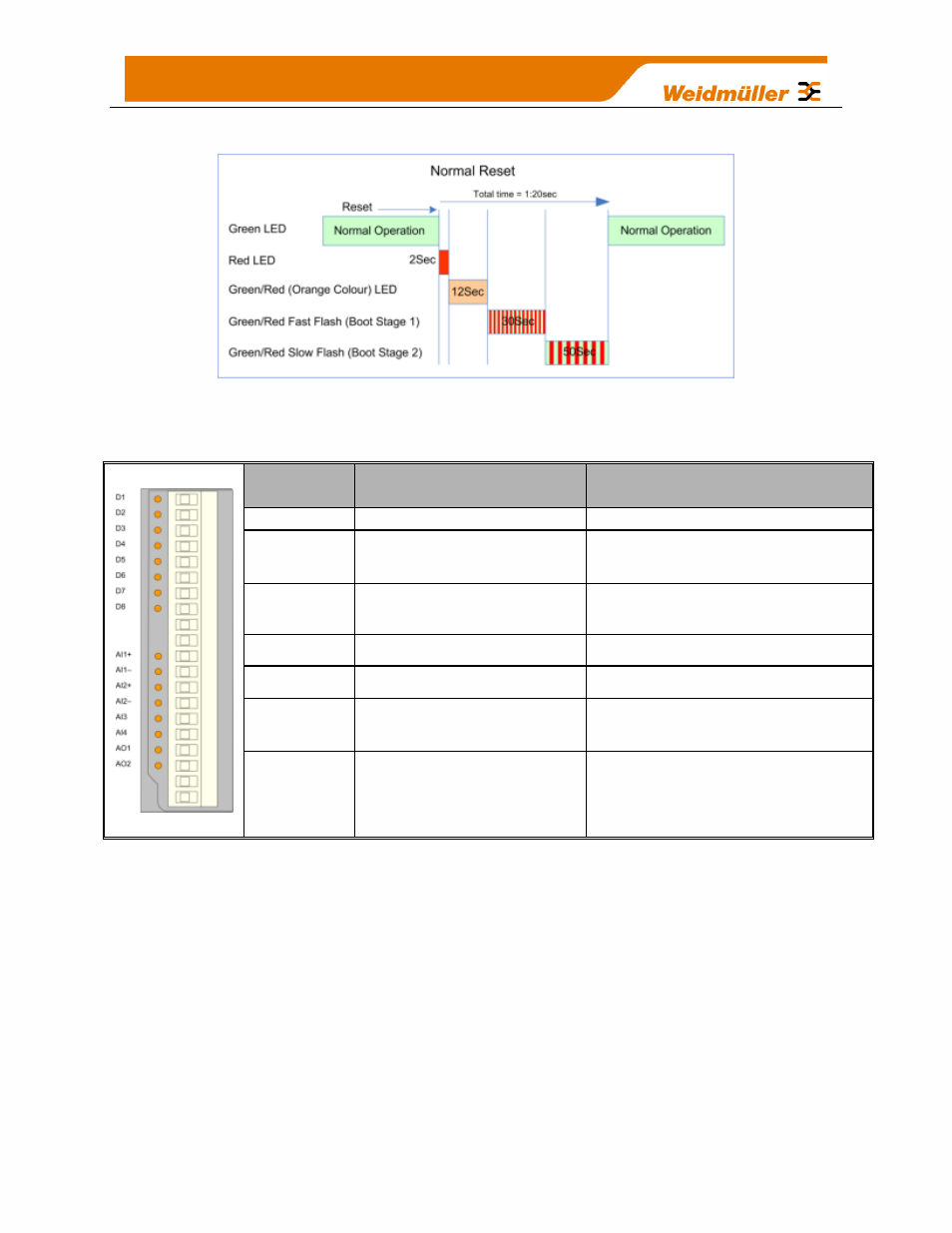
3.2.2 Boot Sequence
“PWR” LED Indications
Figure 22 - Boot Sequence
3.2.3 Input / Output Indications
Digital Inputs
LED’s display the status of each of the eight DIO’s when used as inputs. (If the LED is lit
then the input is on).
Digital Outputs
When the DIO
’s are used as outputs the LEDs will display the status of each of the
digital output (If the LED is lit then the output is on).
The LED’s also indicate if the output
is in a failsafe state by flashing the LED at different rates. If the LED is mostly ON (Long
On) it will indicate the Failsafe state
on the ‘Digital Output Configuration’ page will be
ON and if the LED is mostly OFF (Long Off) it will indicate the Failsafe state will be
OFF. See section 4.3.11
‘Failsafe Blocks’ for more details.
LED
Indicator
Condition
Meaning
D 1- 8
ORANGE
Digital input ON
D 1- 8
FLASHING ORANGE -
(Long On)
Update Failure - Failsafe state
On
D 1- 8
FLASHING ORANGE -
(Long Off)
Update Failure - Failsafe state
Off
AI 1 & 2 +
ORANGE
Analog input current indication
AI 1 & 2
–
ORANGE
Analog input voltage indication
AI 3 & 4
ORANGE
Analog input current or voltage
indication
AO1 & 2
ORANGE
Analog output current indication