Aeris installation and service manual – STEMCO Aeris User Manual
Page 36
Aeris Installation and Service Manual
Page 36 of 42
• Route the wire from the light into the 7 pin connector box. Route enough wire into the box to have about
8” of wire sticking out and cut off excess wire. Strip about 5” of the wire jacket from the wire using a
jacket stripping tool. Make sure not to cut jacket so deep you cut into the insulation on the wires.
• Strip off 1/4" of insulation from the black and white wire.
• Route end of the 3 conductor wire into the 7 pin connector box. Strip the wire jacket from around the
wires back about 6” using a jacket stripping tool. Make sure not to cut jacket so deep you cut into the
insulation on the wires.
• Next strip 1/4” of insulation from the white, brown and yellow wires.
• Crimp a ring terminal on the end of the white wire from the light and crimp a ring terminal on the white
wire going to the control box. Both white wires coming to the 7 pin connector box should have a ring
terminal crimped to them. Use a terminal crimping tool.
• Crimp ring terminal to the brown wire.
• Crimp butt splice to the black wire from the light and the yellow wire from the 3 wire cable going to the
control box.
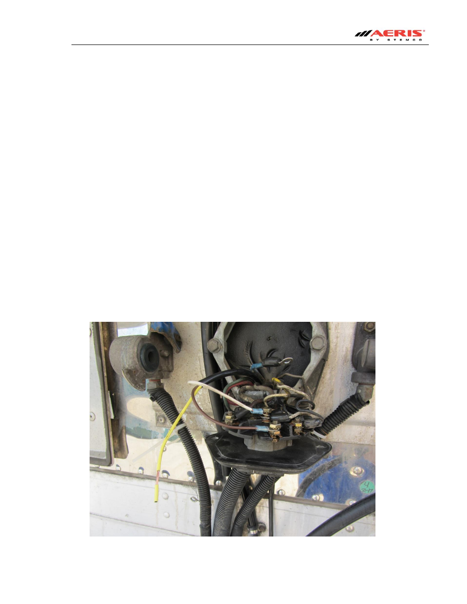
• Remove the nut from (Pin 1 biggest pin) on the 7 pin connector terminal and place both the white wires
from the 3 wire cable and the light on the post. Replace nut and tighten down.
• Remove the nut from (Pin 7) on the 7 pin connector and connect the brown wire from the 3 wire cable to
the post. This will be the center pin and will carry the power on systems that support ABS.
Figure 33