STEMCO 610-0025 Hubodometer User Manual
Installation instructions for stemco hubodometer, Rear wheel truck or bus mount, Important: hubodometer
Printed in the USA
(Hudson 10-491) 09-611-0036
Rev. 07-05
ISO 9001:2000 & ISO/TS 16949
STEMCO-USA
•
P. O. Box 1989
•
Longview, TX 75606-1989
(903) 758-9981
•
1-800-527-8492
•
FAX: 1-800-874-4297
•
www.stemco.com
STEMCO-CANADA
•
5900 Ambler Drive, Units 4 & 5
•
Mississauga, ON L4W 2N3
(905) 206-9922
•
877-232-9111
•
FAX: 877-244-4555
STEMCO and Hubodometer are registered trademarks of STEMCO LP ©2005 STEMCO LP.
Installation Instructions
for STEMCO Hubodometer
®
-
Rear Wheel Truck or Bus Mount
Part Numbers 610-0011 and 610-0025
IMPORTANT:
HUBODOMETER
®
MUST BE ACCURATELY CENTERED ON WHEEL.
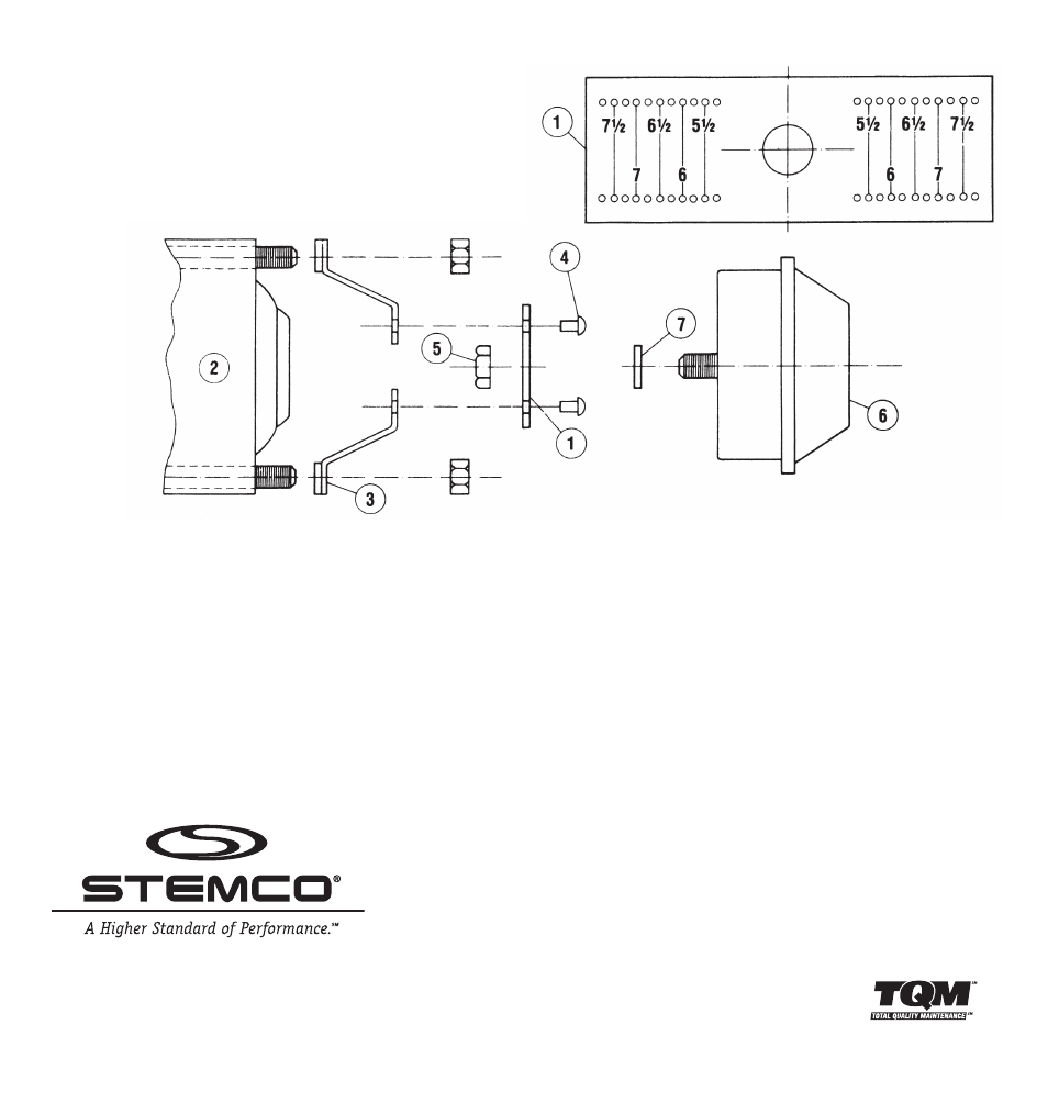
1.
Drill two 3/16" holes on each end of mounting strap (#1) at marks corresponding to bolt circle diameter
of rear wheel axle (#2).
2.
Open single hole in support angles (#3) if necessary to fit axle studs or bolts.
3.
Cut and trim strap 3/8" beyond rivet holes on both ends.
4.
Assemble angles (#3) to mounting strap (#1) as per drawing, using 4 rivets (#4) supplied. Trim angles to conform
to contour of axle if necessary.
5
IMPORTANT: Place washer (#7) on Hubodometer
®
stud.
6.
Mount Hubodometer
®
(#6) on strap using 1/2" locknut (#5) supplied. It is recommended that a strap wrench be
used to hold Hubodometer
®
while tightening. Do not clamp Hubodometer
®
flange in a vise. Do not exceed
15 ft/lbs torque.
7.
Mount strap assembly to axle.
8.
To clean Hubodometer
®
face, use a damp cloth to prevent scrathes. Do not use solvents, paints or thinners.
10-491 Hubodometer Install 7/19/05 3:11 PM Page 1