Step 6, Step 7, Step 8 a – SDC EH SERIES ELECTROMAGNETIC DOOR HOLDER 1224, 24120, 24220 User Manual
Page 3: Step 8c, Catch plate extension rod assembly, Step 9, Step 8 b
P:\INSTALLATION INST\ACCESSORIES\INST-EH SERIES.vsd REV B 08-12 Page 3
DO
OR
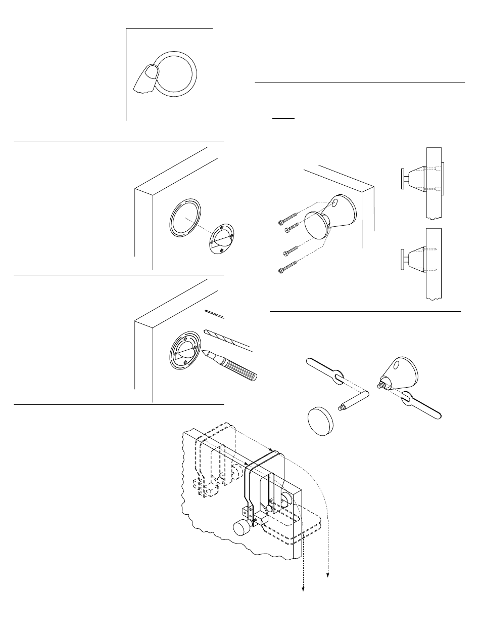
STEP 6:
Opening door will reveal
mounting template. Apply
final pressure to insure
template does not fall off
while assembly takes place.
STEP 7:
Insert alignment template into
center of mounting template.
Use tab to rotate to fine
adjustment. While holding
alignment template with one
hand, remove adhesive
backing of tab, then push flat
against door.
STEP 8 A:
If not using door assembly
drill fixture, center punch
points indicated on
alignment template for either
horizontal or vertical
mounting. For best results,
drill 1/8” pilot holes first, then
follow with 5/16” dia drill.
STEP 8C:
If mounting catch plate assembly directly to door, drill
1/8”dia. pilot hole approximately 1 to 1-1/2” deep,
being careful not to go through door.
CATCH PLATE EXTENSION ROD
ASSEMBLY:
DO
OR
1/8”
5/16”
M
OU
NT
ING TEMP
LA
TE
R
EA
D I NSTR
C
U
TI
O
N
S
DOOR
STEP 9:
For either style of mounting (thru door/direct) remove
ONLY alignment template, then place swivel in center.
Align holes, then insert screws and tighten assembly
fully. Lastly, remove mounting template.
DOOR
DO
O
R
STEP 8 B:
If using door assembly drill fixture,
alignment template is not required.
Locate drill bushing end into mounting
template, holding firmly flat against door,
then tighten slightly. Make sure fixture is
flat against edge of door, tighten fully and
drill through using 5/16” dia. drill.