Display screen, Figure 2-2: display screen component location, Status lights – RKI Instruments Pioneer 4W User Manual
Page 11: Power light, Pilot light, Fail light, Probable causes, Recommended action
Pioneer Gas Monitor Operator’s Manual
Description • 7
Display Screen
NOTE:
The display screen, status lights, and program buttons are mounted to a small
circuit board. The circuit board is mounted to the main circuit board by standoffs.
The display screen is mounted to a circuit board that is installed in front of the main
circuit board. The display screen simultaneously displays the target gas, measuring unit,
and current gas reading of all active channels.
The display screen also displays messages, settings, and other data when you are
operating the instrument programs (see Chapter 4, Operation).
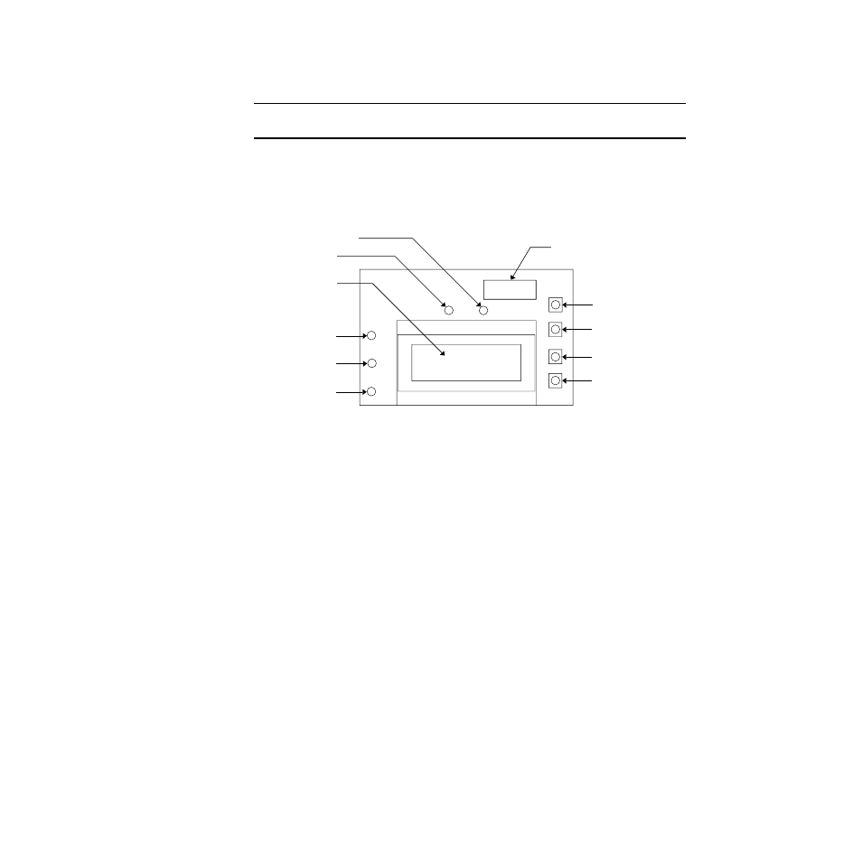
Figure 2-2: Display Screen Component Location
Status Lights
The Pioneer includes six status lights that indicate the current status of the monitor.
POWER light
The POWER light is on the main circuit board near the top edge. The green POWER light
is on when the Pioneer has live power connected and the power switch is in the ON
position.
PILOT light
The PILOT light is above the display screen and to the left of the FAIL light. The green
PILOT light is on when the monitor is receiving incoming power. The PILOT light flashes
when the alarms are disabled. The alarms are disabled during instrument warm up and
when you enter one of the Pioneer’s various programs.
FAIL light
The FAIL light is above the display screen and to the right of the PILOT light. The FAIL
light turns on when the Pioneer is experiencing a fail condition. A fail condition can be
caused by a failure within the monitor or detector(s) wired to the monitor. See Chapter 5,
Maintenance, or the troubleshooting section in the applicable detection insert to respond
to a fail condition.
ESCAPE button
UP/YES button
DOWN/NO button
ENTER button
Display screen
PILOT light
FAIL light
ALARM 3 light
ALARM 2 light
ALARM 1 light
Data logging chip (optional)