Description – RKI Instruments Pioneer 4W User Manual
Page 105
CO Transmitter • 2
Pioneer Operator’s Manual
Description
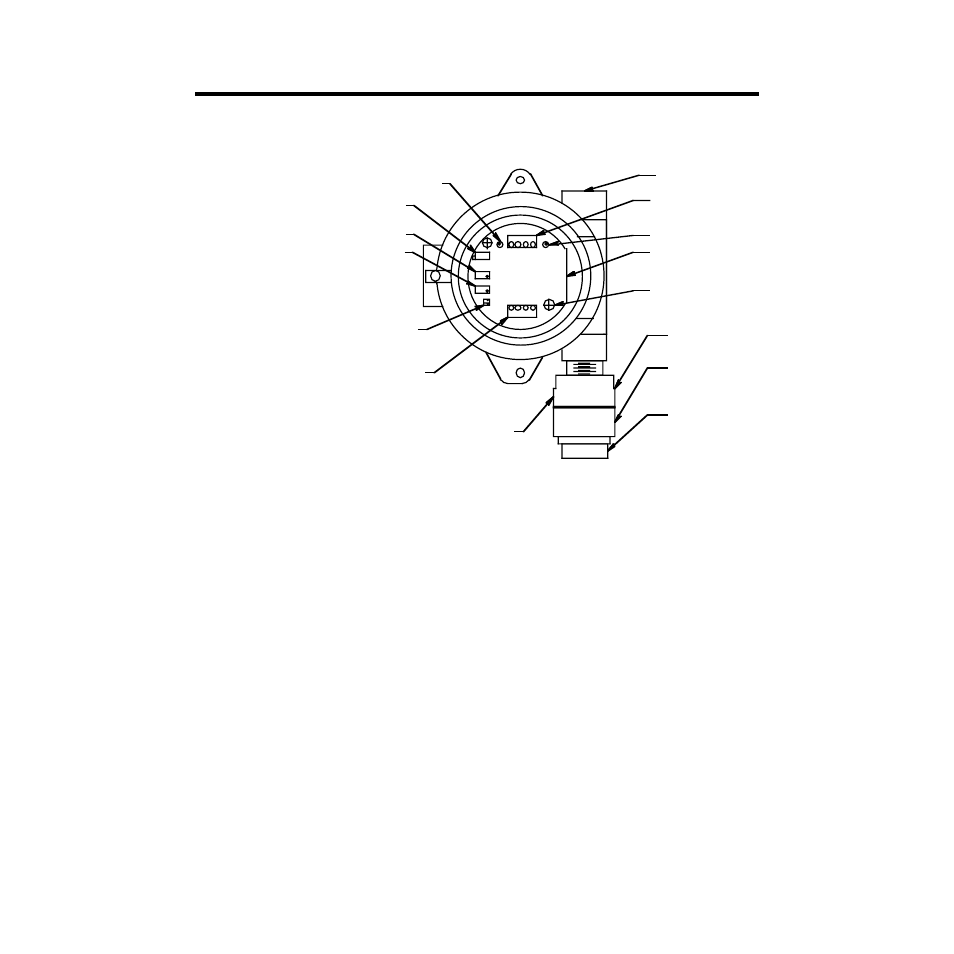
This section describes the components of the CO transmitter. The transmitter consists of
the CO detector, amplifier, and junction box.
Figure 1: CO Transmitter Component Location
CO Detector
The CO detector includes the detector housing, sensor, and filter.
Detector housing
The detector housing protects the sensing components within the housing. Use the
mounting threads at the top of the housing to screw the CO detector into the bottom
conduit hub of the junction box. Use the removable cap near the bottom of the housing to
access the sensor for maintenance or replacement. The cap protects the sensor from
damage and includes a flame arrestor which contains any sparks which may occur within
the detector housing.
Two wires extend from the top of the detector housing. Use these wires to connect the CO
detector to the amplifier. The housing includes a four-socket pattern. This socket pattern
accepts the sensor’s four pins to secure the sensor within the detector housing. A pre-
amplifier, located between the sockets and two interconnect wires, conditions the sensor’s
signal before the signal reaches the amplifier.
Factory Set
Potentiome ter
Zero P otentiometer
Span Potentiome ter
Flame Arrestor
Detector Housing
Detector Housing
Cap
Interconnect Terminal
Strip
Carbon Monoxide
Amplifier
Jumper Block Installed To
Toxic Select Header
Detector Terminal Strip
T est P oint (-)
3 /4" Conduit Hub
Test Point (+)
Securing Screw (2)
Carbon Monoxide Detector