RKI Instruments Pioneer 4W User Manual
Page 109
CO Transmitter • 6
Pioneer Operator’s Manual
6.
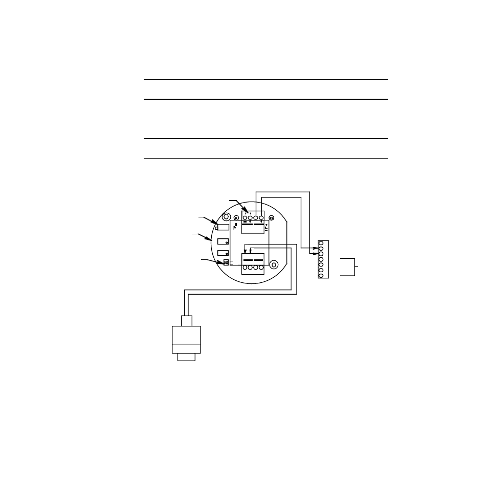
Connect the two wires to the interconnect terminal strip as follows (see Figure 3.)
•
Connect the positive wire to the terminal labeled
24V +
.
•
Connect the feedback wire to the terminal labeled
4/20 FB
.
CAUTION:
Leave the ground wire insulated and disconnected at the transmitter. You will
connect the opposite end of the cable’s ground wire at the Pioneer.
7.
Secure the junction box cover to the junction box.
8.
Route the cable or wires leading from the CO transmitter through one of the conduit
hubs on the bottom of the Pioneer housing.
CAUTION:
Do not route power and transmitter wiring through the same conduit hub. The
power cable may disrupt the transmission of the transmitter signal to the Pioneer.
9.
Connect the wires to the detector terminal strip of the applicable analyzer card as
shown in Figure 3. The detector terminal strip is the 7-point terminal strip (terminals 1
through 7) on the card.
Figure 3: Wiring the CO Transmitter to the Pioneer Gas Monitor
10. At the Pioneer, connect the cable’s ground wire to an available chassis ground. The
grounding screw on each conduit hub is an example of a chassis ground.
CO Detector,
Factory Wired
Jumper Block
Installed To Toxic
Select Header
Individual Amp/Detec tor
Terminals
Not
Used
F actory Set Pot
Red
Not Used
Toxic Amplif ier
Assembly
Black
24V
4/2 0
TOXIC
Z ERO
OXY
B ATT
FB
SPAN
TOXIC
G
GND
FB (4/20)
24V
GRN
BLK
RED
WHT
W
R D
B K
OXY