Sh eet, Instr u ction – Prescolite 8MD REFLECTOR User Manual
Page 2
Instr
u
ction
Sh
eet
Part No...........................................
With representatives offices in principal cities throughout North America.
Copyright , revision, All Rights Reserved - Printed in U.S.A.
701 Millennium Blvd • Greenville, SC 29607
www
.p
re
s
c
o
lit
e
.c
o
m
y
Prescolit
e
T
o
ll Free
T
e
c
hnic
a
l S
u
pp
ort
1.
88
8.
PR
S.
4TEC
y
Ho
u
rs
: 8a
m
-
5p
m
ET
93047835
2013
04/12/13
FIG. 1
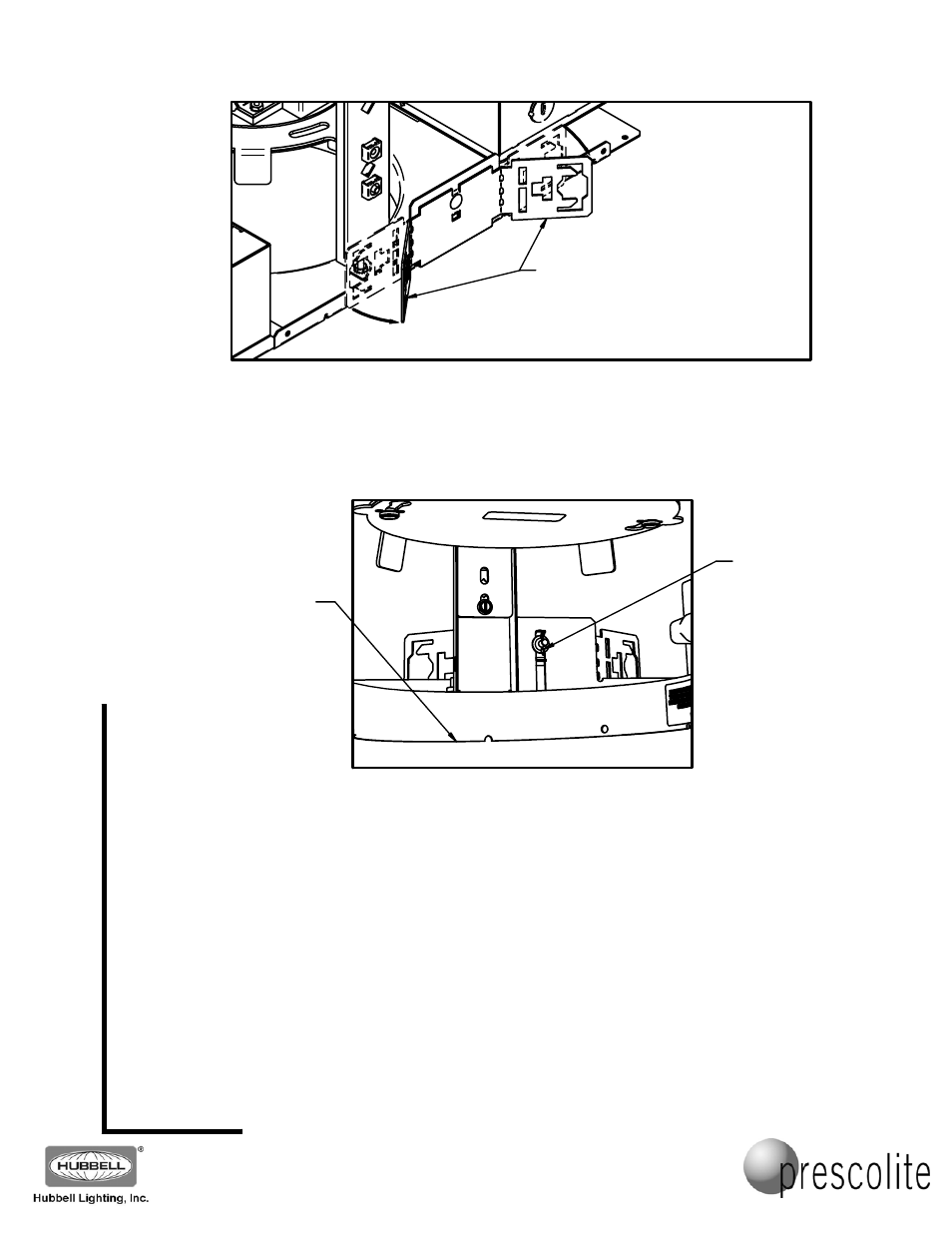
3. Adjust the fixture vertically by loosening the wing nuts on the adjustable mounting brackets on either
side of the fixture. Important - adjust the fixture height so the bottom of the plaster flange is
flush with the finished ceiling line and in alignment with adjacent fixtures. (See FIG. 2) Once
adjusted correctly, lock the adjustable mounting brackets by securely retightening both wing nuts.
FIG. 2
4. Determine where the supply wiring conduit will enter the J-Box, remove the appropriate J-Box
knockout, and attach the conduit.
NOTE: Make all conduit and wiring connections to the fixture in conformance with the National
Electrical Code.
5. Remove the J-Box cover plate and connect the fixture wiring using the appropriate connectors for the
supply wires used. Connect the supply ground wire to the green (ground) fixture lead. Connect the
white (common) supply wire to white fixture lead. Connect the power supply (line) to black fixture lead.
Make any control wiring connections to the control input leads (violet and gray leads for 0-10V
dimming on the standard fixture). IMPORTANT: If the control leads are not used, individually cap
off the unused leads.
Reinstall J-Box cover.
WARNING: DO NOT pinch wires between J-Box cover and J-Box. Consult a Qualified
Electrician for all other options that require other wiring configurations.
THE ADJUSTABLE MOUNTING
BRACKETS ARE SUPPLIED FLAT.
BEND AS SHOWN TO ACCEPT THE
OPTIONAL B6 OR B24 BAR HANGERS,
OR MOUNTING CHANNEL OR BAR
(BY OTHERS).
ADJUSTABLE
MOUNTING
BRACKET WING
NUT (ONE ON
EITHER SIDE OF
THE PLASTER FRAME)
MAKE SURE EDGE
OF PLASTER
FLANGE IS FLUSH
WITH THE FINISHED
CEILING LINE.
PAGE 2 OF 7