Opticon PHL 1700 User Manual
Page 7
U
SER
’
S MANUAL
PHL 1700
LASER TERMINAL
/ IRU 1700
CRADLE
7
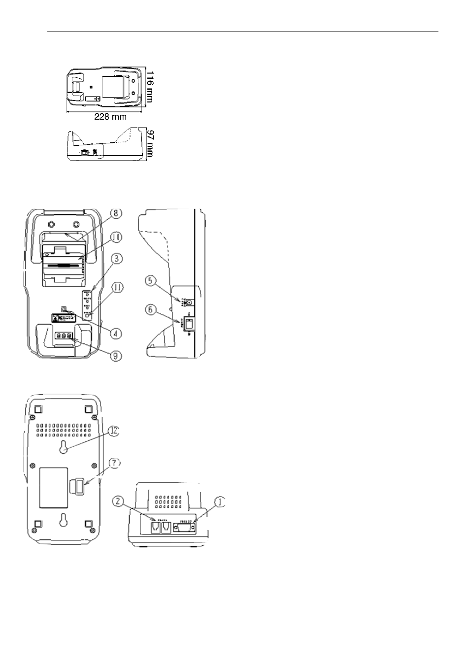
2.2.4 Dimensions of the cradle
2.2.5 Details of cradle
1. RS 232 C socket
for connecting to PC or modem, through
Opticon RS232 cable
2. RS 485 socket
for connecting another cradle in multi-drop
RS485 network, through Opticon RS485
cable
3. LED indicator
indicating status of:
POWER
red
: power on
green: terminal is on cradle
SD/RD
red
: receive data
green: send data
BATT *
red
: charging battery
green: charging is ready
*) BATT status is only for model TC and SV
4. Switch for terminal detection
to detect if a terminal is placed on the
cradle
5. DC input socket
input for AC adaptor
6. Power switch
7. DIP switches
setting parameters of the infra red interface
switches are located behind the cover
8. Data Transmission
Interface for optical data transmission
9. Contact for recharging
only for the model SV and TC
10. Battery spare slot for recharging
quick charge NiMH pack
only for the model transceiver/charger
11. Refresh switch
refresh-discharge NiMH pack
only for the model transceiver/charger
12. Wall mounting holes
- С-37 Universal menubook (151 pages)
- С-37 (8 pages)
- CHG 3101 (2 pages)
- CRD 3101 (4 pages)
- CRD 13 (4 pages)
- CRD 15 (1 page)
- CRD 1531 (1 page)
- CRD 19 E4 (1 page)
- CRD 19 E4 AdminTool (11 pages)
- OPL 972X (23 pages)
- DCL 153X (23 pages)
- DFM 1000 (20 pages)
- DWT 7133 (9 pages)
- ECB 1000 (12 pages)
- ESL (40 pages)
- H13 (4 pages)
- H15 Quick Guide (2 pages)
- H15 User Manual (101 pages)
- H16 End User License Agreement for Microsoft Software (8 pages)
- H16 Quick Guide (2 pages)
- H16 User Manual (160 pages)
- H19 User Manual (192 pages)
- H19 Cradle User Manual (2 pages)
- H19 Quick Guide (2 pages)
- H19 car kit Quick Guide (1 page)
- H21 (103 pages)
- H22 (110 pages)
- M5 (4 pages)
- OPD 7124 brief setup (4 pages)
- OPH 1003 (2 pages)
- OPH 1004 (2 pages)
- OPH 1005 (2 pages)
- OPI 2101 (4 pages)
- OPI 4002 (26 pages)
- OPL 9713 (1 page)
- OPL 9724 Bluetooth Print (9 pages)
- OPL 9724 (29 pages)
- OPL 9728 (19 pages)
- OPM 1736B (8 pages)
- OPN 2001 User Manual (11 pages)
- OPN 2001 Device Parameters (3 pages)
- OPN 2002 v35315 Bluetooth demo Quick Guide (13 pages)
- OPN 2002 v35412 Batch demo Quick Guide (14 pages)
- OPN 2002 v35106 Bluetooth OPN2001 simulation Quick Guide (11 pages)
- OPN 2002 Quickstart Guide for iPhone or iPad (2 pages)