Operation – Multiquip WRS5200 (ORIGINAL COPY) User Manual
Page 47
wrs5200 hydraulic roller screed • operaTion manual — rev. #1 (10/22/10) — page 47
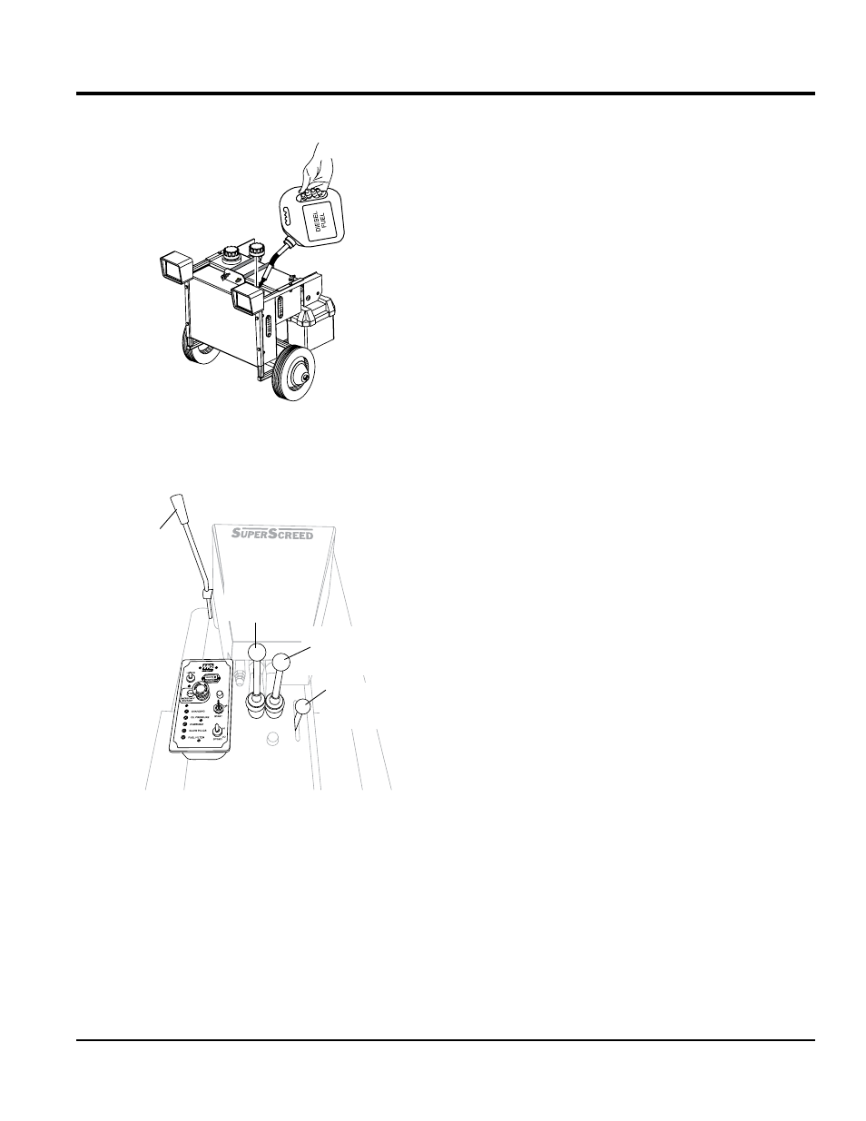
3. If the hydraulic oil level is low, remove the hydraulic oil
cap (Figure 37) and fill with type ISO 46 anti-wear type
hydraulic oil to the recommended operating level.
Figure 37. Adding Hydraulic Oil
sTarTing
Reference Figure 38.
Figure 38. Lever Operation
1. On the power unit place the operation valve lever in the
screed position (See Figure 12, item 12).
2. Sit down in operator's seat and pull safety bar inward
towards your body.
3. Place the two drive tube directional control levers in
the
middle position.
4. Place the drive tube speed control lever in the
straight
up position.
OPERATOR END
DIRECTIONAL
DRIVE TUBE
CONTROL LEVER
ENGINE END
DIRECTIONAL
DRIVE TUBE
CONTROL LEVER
DRIVE TUBE
SPEED CONTROL
LEVER
STRIKE TUBE
SPEED AND
DIRECTIONAL
CONTROL LEVER
OperatiOn
5. Place the strike tube speed and directional control lever
in the
neutral (center) position.
6. Pull upwards on the emergency stop switch.
7. Place engine speed switch in the
LO position.
8. Insert ignition key into ignition switch. Next, turn ignition
key to the
on position. This position allows warming of
the glow plugs.
9. When glow plug status LED goes off, turn ignition key
to start position.
10. Let engine idle for 2 to 3 minutes. Listen for any
abnormal sounds.
11. Verify that all engine status LED's on the control box are
OFF. If any status LED's are on, shutdown the engine
and correct the problem.
12. Place engine speed switch in the
HI position.
operaTion
1. Fully engage the
operator end directional drive tube
control lever in the forward direction.
2. Move the drive tube speed control lever slightly forward
(a few rpm's) and verify that both drive tubes rotate.
3. Fully engage the
operator end directional drive tube
control lever in the reverse (pull back) direction.
4. While drive tube is rotating, push safety bar forward
and verify that drive tube rotation stops.
5. Return operator end directional drive tube control lever
to center position.
6. Move the
power unit end directional drive tube control
lever fully forward and verify that both drive tubes
rotate.
7. Next, fully engage the
power unit end drive tube
control lever in the reverse (pull back) direction and
verify that both drive tubes rotate.
8. Return power unit end directional drive tube control
lever to center position
9. Place the drive tube speed control lever in the
straight
up position (off).
10. Move the strike tube speed and direction control lever
slightly forward. Verify strike tube rotates in a clockwise
rotation. Move lever slightly backwards and verify that
strike tube rotates in a counter-clockwise direction.
11. Screed is now ready for use.