Control box components – Multiquip WRS5200 (ORIGINAL COPY) User Manual
Page 28
page 28 — wrs5200 hydraulic roller screed • operaTion manual — rev. #0 (10/22/10)
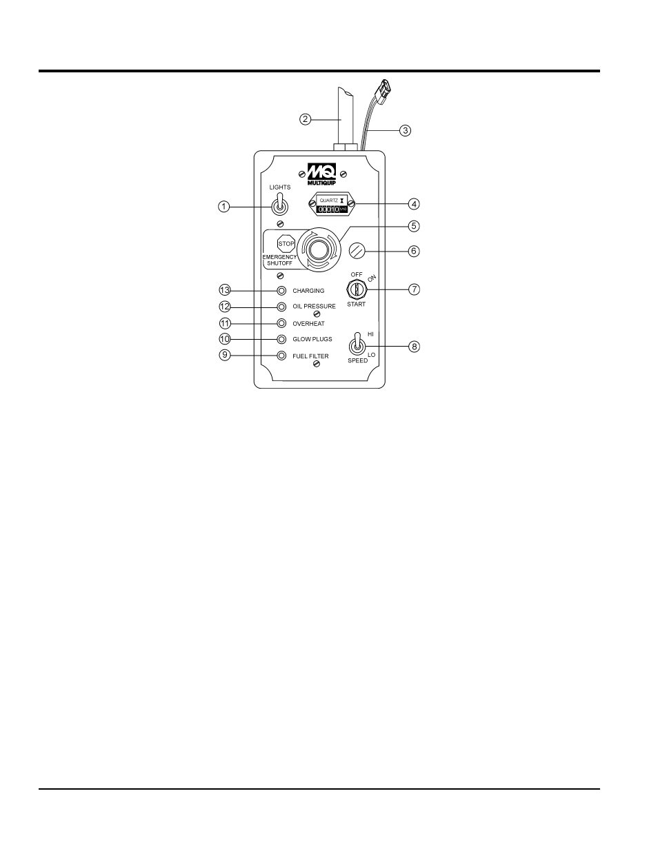
Figure 13. Control Box
cOntrOl bOx cOMpOnentS
The definitions below describe the controls and functions
of the Control Box (Figure 13).
1.
light switch — Activates halogen lights. Lighting to
be used at night or in dark areas.
2.
data cable — Provides electrical control signals
between control box and Power Unit.
3.
solenoid Bypass valve connector — Provides an
electronic signal to solenoid valve to stop the hydraulic
pressure flow to the drive tubes in the event the operator
leaves the operators seat during operation.
4.
hour meter — Displays the number of hours the
machine has been in use.
5.
emergency stop Button — In the event of an
emergency press this switch.
do noT use this button
as a method of shutting down the unit. Pull button
outward when re-starting.
6.
fuse holder — 15 amp fuse. Always replace with
recommened type and size fuse.
7.
ignition switch — When starting in cold weather
conditions, place ignition switch in the start position
and allow glow plugs to warm.
8.
engine speed switch — Controls engine speed. For
normal operation place this switch in the HI position.
9.
fuel filter led — Illuminates when water has has
collected in the fuel filter. Drain fuel filter if light stays
on.
10.
glow plugs led — Indicates glow plugs are being
heated. When LED is extinguished (OFF) engine can
be started.
11.
overheat led — Illuminates when engine has
overheated. Check coolant level When this condition
occurs, shutdown engine immediately and correct the
problem.
12.
oil pressure — Illuminates when engine oil pressure
is low. Shutdown engine immediately and correct the
problem
13.
charging — Illuminates when charging system is not
working correctly. Shutdown engine immediately and
correct the problem.