Roller screed assembly – Multiquip WRS5200 (ORIGINAL COPY) User Manual
Page 39
wrs5200 hydraulic roller screed • operaTion manual — rev. #1 (10/22/10) — page 39
rOller ScreeD aSSeMblY
Strike Tube Installation (Engine End)
The 16 ft. (4.87 meters) strike tube section should now
be attached to the matching middle section of truss. The
following section will illustrate joining the engine section
of strike tube.
1. The second middle bracket should now be installed
with the splined shaft supporting one end of the 16 ft.
(4.87 meters) strike tube. The other end of the splined
shaft should be exposed.
2. Insert one end of the 14 ft. (4.25 meters) strike tube
onto the exposed-end of the splined shaft located on
the
second middle bracket (Figures 22).
3. Verify that the strike tube bearing has been (Figure 22)
mounted on outer plate at engine end of the screed. If
bearing has not been installed, please see next step.
Otherwise proceed to step 5.
4. Secure strike tube bearing to outer plate (engine end)
with 7/16-14x2 HHSC screws (2) and 7/16 nyloc nuts
(2). Torque bearing support nuts to 75 ft.-lbs ( 102
N.m)
5. Next, insert the other end of the strike tube into the strike
tube bearing located on the outer plate (engine end).
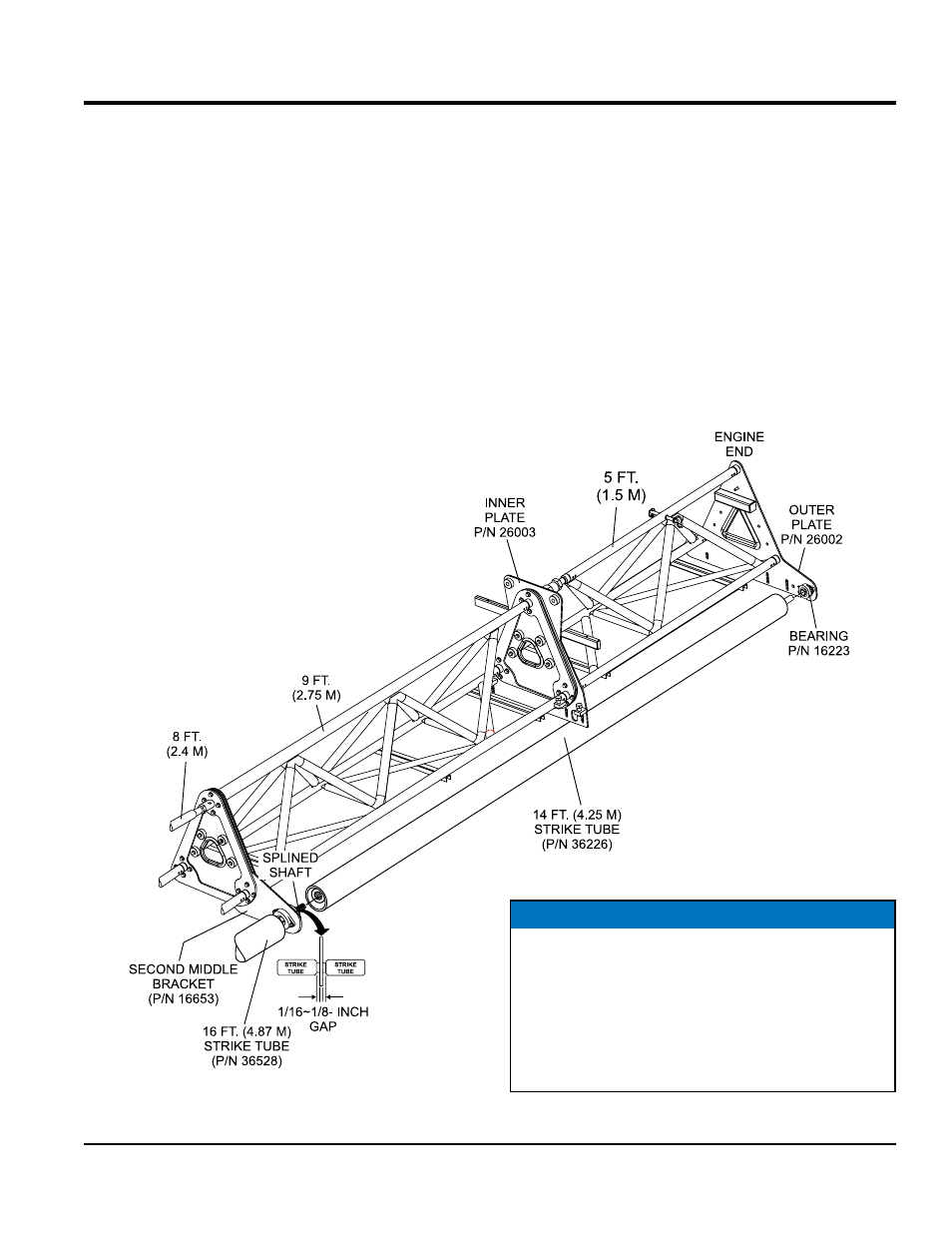
Figure 22. Strike Tube Engine End (14 ft./4.25 m)
NOTICE
The strike tube adjustment nut should be adjusted so
that the inner edge of the strike tube next to the middle
bracket is spaced between 1/16 to 1/8 inch. Please note
the strike tube will bottom out on the splined shaft when
a gap of less than 1/16 of an inch between the strike
tube and middle bracket remains. Further adjustment
will bend the outer plate.