Ride-on roller screed components – Multiquip WRS5200 (ORIGINAL COPY) User Manual
Page 24
page 24 — wrs5200 hydraulic roller screed • operaTion manual — rev. #0 (10/22/10)
riDe-On rOller ScreeD cOMpOnentS
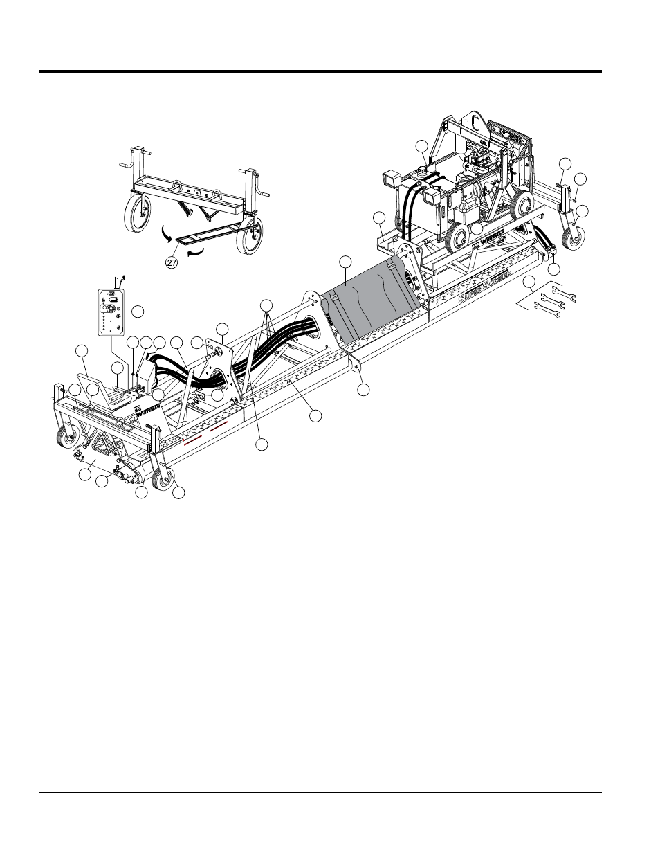
Figure 11. Power Unit Components
S
S
UPER
CREED
S
S
UPER
CREED
WRS5200
1
2
STOP
EMERGENCY
SHUTOFF
LIGHTS
SPEED
HI
LO
CHARGING
OIL PRESSURE
OVERHEAT
GLOW PLUGS
FUEL FILTER
START
OFF
ON
00010 1/10
QUARTZ
4 5
3
6
7
9
10
11
12
13
14
15
16
17
19
18
21
23
24
25
27
20
28
26
22
25
8
29
The definitions below describe the controls and functions
of the Ride-On Power Screed (Figure 11).
1.
operators seat — Provides an unobstructed view of
the work area. Seat is adjustable.
2.
safety Bar — When pushed forward, rotation of both
sets of drive tubes will stop.
3.
control Box — Provides vital engine status information
via LED's. Also contains emergency stop switch,
ignition switch halogen light switch and engine speed
switch and hour meter. One xx amp fuse required.
Replace with only recommended type fuse.
4.
drive Tube lever (engine side) — When activated this
3 position lever will cause the
engine side drive tube to
to rotate in a clockwise (forward) or counterclockwise
(reverse) direction. The center position is neutral, no
rotation. This drive tube is independent of the operator
side drive tube.
5.
drive Tube lever (operator side) — When activated
this 3 position lever will cause the
operator side
drive tube to rotate in a clockwise (forward) or
counterclockwise (reverse) direction. The center
position is neutral, no rotation. This drive tube is
independent of the engine side drive tube.
6.
drive Tube speed control lever — Controls the
variable speed of the drive tubes. 150 rpm max. This
lever should be in the
straight up position when
starting the engine.