Roller screed assembly – Multiquip WRS5200 (ORIGINAL COPY) User Manual
Page 40
page 40 — wrs5200 hydraulic roller screed • operaTion manual — rev. #0 (10/22/10)
rOller ScreeD aSSeMblY
Task 8: strike Tube motor mounting
For initial setup the strike tube motor can be located on
the power unit (Figure 12, item 9. It is held in place by two
circular support bosses which are welded to the frame of
the power unit.
Remove the pin hitch clip that secures the motor to the
power unit frame and perform the following:
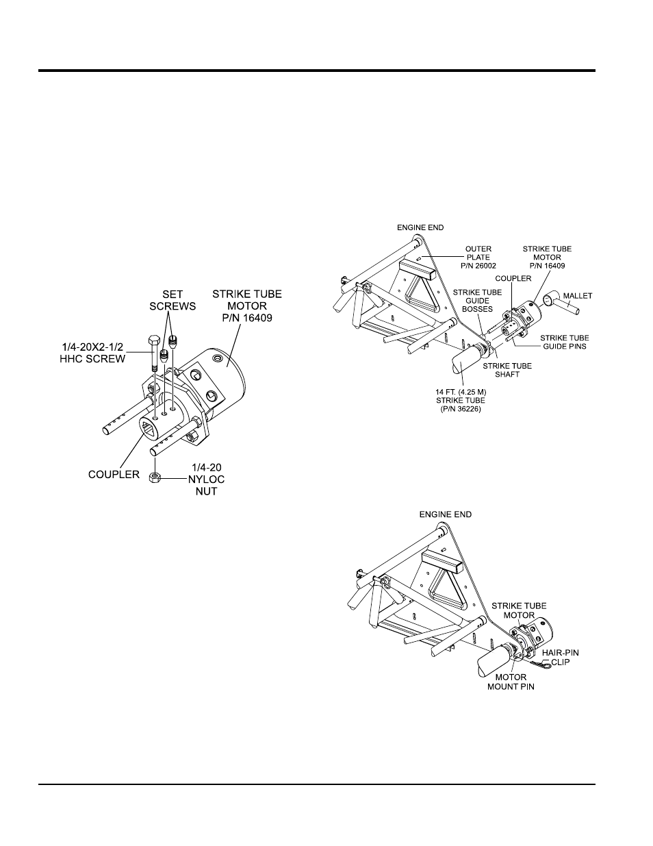
1. Make sure the two set screws (Figure 23) on the
coupler have been retracted enough to allow the
coupler to slide easily onto the strike tube shaft.
2. Second make sure that the shaft retaining screw and
nut have been removed from the coupler.
Figure 23. Strike Tube Motor
3. Insert strike tube motor coupler (Figure 23) onto shaft
of strike tube. Additionally insert strike tube guide pins
into guide bosses located on outer plate.
4. Once coupler and guide pins have been properly
aligned onto strike tube shaft, tap back-end of strike
tube motor with a mallet until first hole on coupler is
aligned with strike tube shaft hole.
5. Using an allen-wrench. Insert both set screws into
coupler. Tighten each set screw securely.
6. To prevent the strike tube from dislodging, insert the
1/4-20X2-1/2 HHC screw into first hole on the coupler
and thru the strike tube shaft. Tap the screw slightly if
necessary.
7. Use a 1/4-20 nyloc nut to secure the screw in place.
Tighten securely.
Figure 24. Securing Strike Tube Motor
8. To prevent the strike tube motor from dislodging, insert
hair-pin clip into strike tube motor mount pin as shown
in Figure 25.
Figure 25. Installing Hair-Pin Clip