Swift 30a or swift 30t viewed from pilot side – MTS SWIFT 30 Sensor User Manual
Page 79
Test Track Vehicle
SWIFT 30 Sensors
Installing the Transducer
79
5. Attach the hub adapter to the transducer. Hand tighten the bolts.
If environmental conditions warrant, coat each fastener with Birchwood
Casey Sheath RB1 rust preventative (or equivalent).
Lubricate the threads and under the heads of all fasteners, using Molykote
g-n paste.
A clearance of approximately 0.05 mm (0.002 in) is required between the
transducer and the hub adapter. You should not have to wedge the wheel into
the rim or the hub adapter into the SWIFT sensor.
Bolt Torque Sequence
6. Tighten the mounting bolts.
A. Following the sequence shown in the previous figure for the transducer
being installed, torque the four M8 inner hub bolts in two increments as
shown in the following table.
Important
The M8 bolts in the inner bolt pattern (bolts A–D in the previous
figure) must be torqued, as described, before torquing the M10
bolts.
B. Following the sequence shown in the previous figure for the transducer
being installed, torque the twenty-four M10 inner hub bolts in two
increments as shown in the following table.
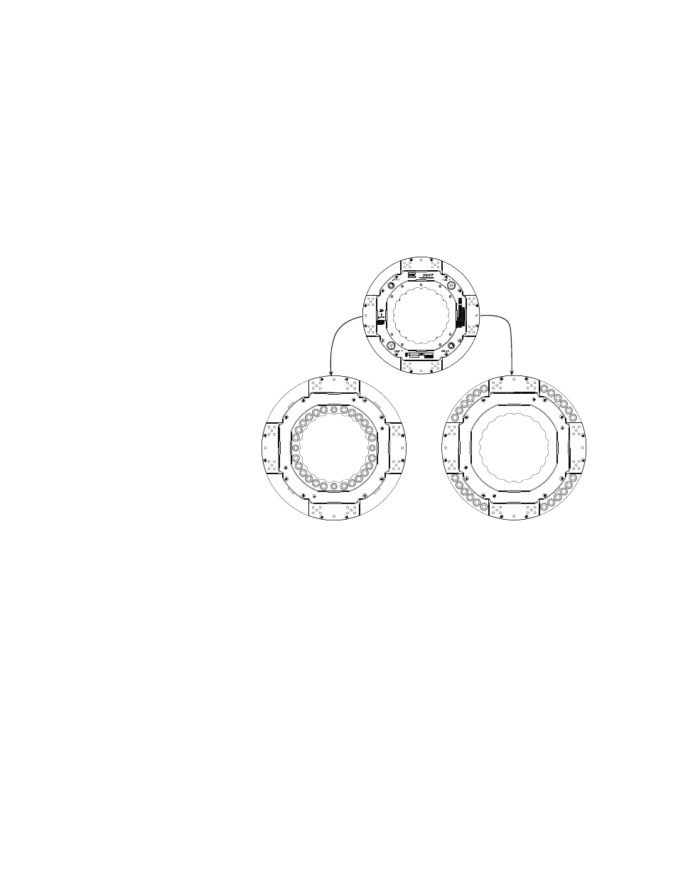
SWIFT 30A or SWIFT 30T
Viewed from Pilot Side
S30-16
Inner Bolt Pattern
Bolts AD are M8
Bolts 124 are M10
Outer Bolt Pattern
All bolts are M10
B
A
8
4
16
11
19
23
14 2
D
6 10
18
22
15
3
7
12
20
24
13
21
17
9 5
C
1
4
16
21
17
9
5
1
13
24
20
12
7
3
15
22
18
10
6
2
14
23
19
11
8